Image forming apparatus

a technology of image forming apparatus and forming apparatus, which is applied in the direction of electrographic process apparatus, instruments, optics, etc., can solve the problems of affecting the image density

Active Publication Date: 2005-09-22
CANON KK
View PDF12 Cites 6 Cited by
  • Summary
  • Abstract
  • Description
  • Claims
  • Application Information

AI Technical Summary

Benefits of technology

[0008] It is an object of the present invention to provide an image forming apparatus capable of appropriately performing recovery operation after the output of a density sensor falls into an error level.

Problems solved by technology

However, even when the image density is controlled by a bias using the developer density detecting sensor and the image density sensor as discussed above, fogging is likely to occur due to excessive supply of toner if the developer density is forcedly recovered at the time of recovery operation subsequent to detection of an anomalous condition of the developer density.
Even in the event that no fogging appears, variation in the image density is liable to occur.

Method used


Image

  • Image forming apparatus
  • Image forming apparatus
  • Image forming apparatus

Examples


first embodiment

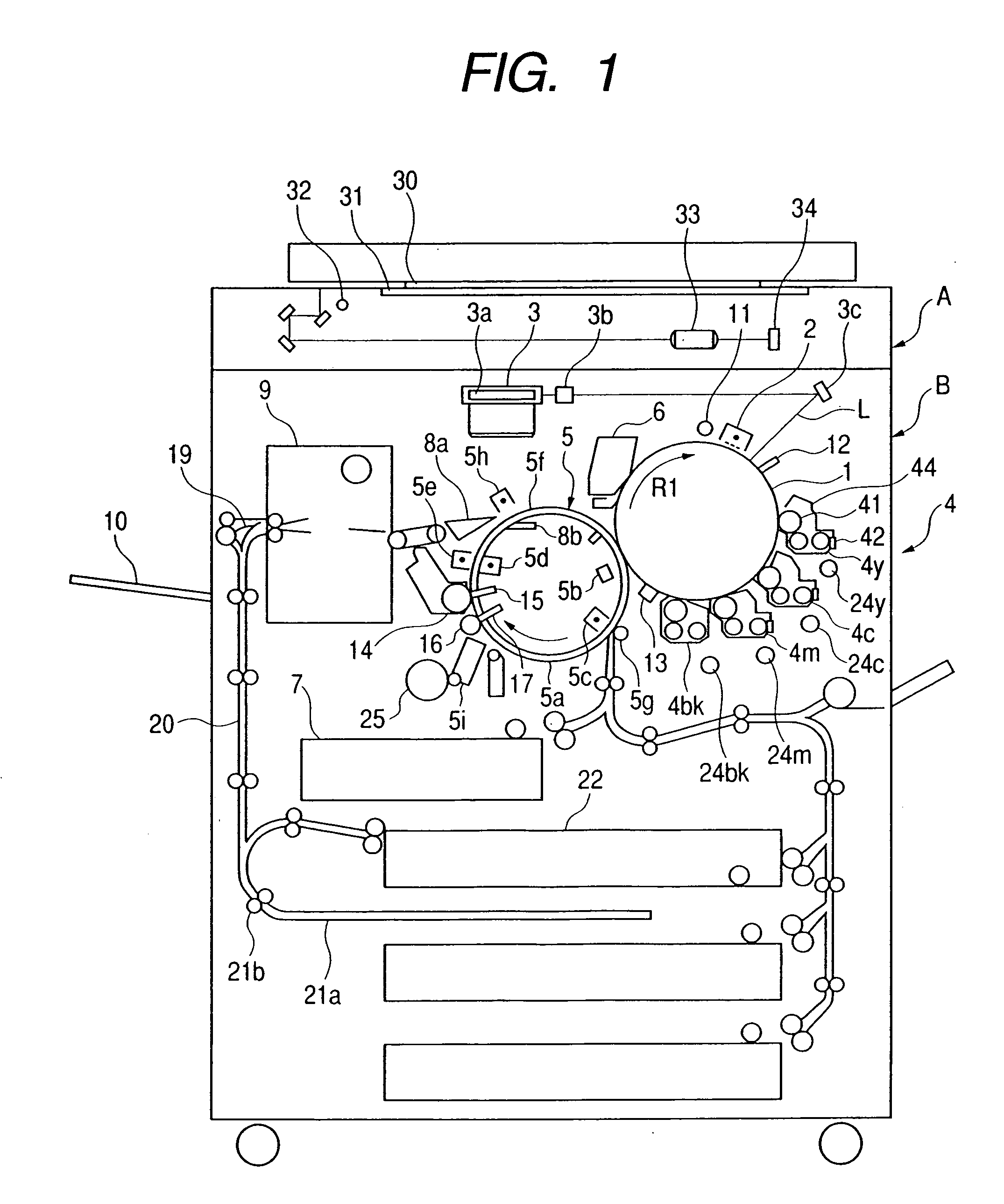
[0019]FIG. 1 illustrates an image forming apparatus of a first embodiment according to the present invention. The image forming apparatus illustrated in FIG. 1 is directed to a four-color full color image forming apparatus of an electrophotographic system and a digital system. FIG. 1 is a longitudinal cross-sectional view schematically illustrating the structure of the image forming apparatus.

[0020] The image forming apparatus illustrated in FIG. 1 has an upper portion of a digital color image reader portion (simply referred to as a reader portion in the following description) A, and a lower portion of a digital color image printer portion (simply referred to as a printer portion in the following description) B.

[0021] In the reader portion A, an original 30 is placed on an original support glass 31, a reflected-light image generated by exposure-scanning the original 30 with an exposure lamp 32 is condensed onto a full color sensor 34 by a lens 33, and color separation image signal...

second embodiment

[0073] With respect to supply of toner, especially occurrence of fogging at the time when toner is a little excessively supplied, its influence is particularly large in a cleaner-less image forming apparatus. There is a great fear that a foggy image is moved together with the photosensitive drum, and interrupts charging to further enhance the fogging.

[0074] A second embodiment is therefore directed to a cleaner-less image forming apparatus.

[0075] The image forming apparatus has image formation processes such as charging, exposure, development, transfer, fixation and cleaning. In an image forming apparatus with a cleaner, toner (non-transferred residual toner) remaining on the surface of a photosensitive drum 1 after transferring operation is collected by a cleaning unit (cleaner) to be waste toner. It is preferable from the standpoints of environmental protection and so forth that no waste toner is generated.

[0076]FIG. 6 schematically illustrates a cleaner-less type image forming...


PUM


Abstract

An image forming apparatus includes a developing device for developing an electrostatic image formed on an image bearing member with developer including toner and carrier, a density sensor for detecting a density of the toner, a control unit for controlling the amount of toner to be supplied to the developing device by comparing an output of the density sensor with a target value, a changing unit for changing the target value when the output of the density sensor falls into an error level, and a recovering unit for supplying the toner based on the target value changed by the changing unit to perform a recovery operation.

Description

BACKGROUND OF THE INVENTION [0001] 1. Field of the Invention [0002] The present invention relates to image forming apparatuses using electrophotographic systems and electrostatic systems, and particularly to image forming apparatuses such as copying machines, printers, and facsimile apparatuses. [0003] 2. Related Background Art [0004] In image forming apparatuses, such as copying machines, printers, and facsimile apparatuses, using as developer tow-component developer with main components of toner and carrier, toner is spent and a developer density in a developing apparatus gradually decreases as image formation proceeds. [0005] Accordingly, the developing apparatus is equipped with a toner supplying apparatus for supplying toner, and toner in the toner supplying apparatus is occasionally supplied to the developing apparatus based on an output of a sensor for sensing the density of developer in the developing apparatus, such that the density of developer in the developing apparatus ...

Claims


Application Information

Patent Timeline
Patent Type & Authority Applications(United States)
IPC IPC(8): G03G15/08G03G15/00G03G15/10G03G21/00
CPCG03G15/5041G03G15/0893G03G15/0856G03G15/0849
Inventor OGATA, TAKAO
Owner CANON KK
Why Eureka
Try Eureka