Printing apparatus, print head performance recovery device and method, and piston pump

a technology of performance recovery and printing head, which is applied in the direction of printing and other printing apparatus, can solve the problems of increased apparatus body size in the movement direction reduced size, and increased operation according to the position of the moving carriage, so as to reduce the cost of the apparatus, improve the efficiency of operation, and improve the effect of siz

Inactive Publication Date: 2006-08-29
CANON KK
View PDF12 Cites 6 Cited by
  • Summary
  • Abstract
  • Description
  • Claims
  • Application Information

AI Technical Summary

Benefits of technology

[0064]With this invention, a first drive mechanism and a second drive mechanism are used to perform a recovery operation for maintaining the printing performance of the print head. The first drive mechanism uses as its drive source a first drive source for driving a transport means to transport the print medium and operates through a clutch mechanism according to a driving force generating direction of the first drive source, the clutch mechanism being adapted to transmit a rotation in only one direction of the first drive source. The second drive mechanism uses as its drive source a second drive source for driving a feeding means to feed the print medium to the transport means, has a dead zone in which a rotational force is not transmitted to the feeding means when the second drive source changes its rotation direction, and operates in the dead zone according to a driving force generating direction of the second drive source. This arrangement makes it possible to control the first drive mechanism and the second drive mechanism with ease by simply switching the driving force generating direction of the first drive source and the second drive source.
[0065]This in turn eliminates the need for a complex drive transmission switching mechanism which would be required in performing the recovery operation, resulting in a smaller size, simpler construction and lower cost of the apparatus.
[0066]With this invention, a mechanism for converting a rotary motion of the rotating body into a linear motion of the piston shaft can be constructed easily by fitting a projection of the rotating body into a continuous spiral groove formed in the piston shaft. As a result, particularly in those printing apparatus required to meet higher standards of compactness and portability, it is possible to construct a piston pump suited for use in the recovery operation for maintaining the print head performance.

Problems solved by technology

The constructions disclosed in Patent References 1–4, however, change an output destination of the driving force according to the operation of the carriage and therefore have the following problems.
This raises a problem of an increased apparatus body size in the carriage movement direction.
Further, the construction of Patent Reference 4 requires a complex mechanism for each of the wiping, suction and paper feeding operations to switch the output destination of the driving force of the third drive source.
Furthermore, the problems still remain that the switching operation according to the position of the moving carriage takes an additional time and that the size reduction, simple construction and low cost are compromised.
This type of tube pump therefore is not suited for reducing an overall size of the recovery device.
However, to reciprocate the piston shaft 626 requires repetitive rotation of the cam 8 and It is also necessary to control the amount of rotation, making this driving method complex.

Method used


Image

  • Printing apparatus, print head performance recovery device and method, and piston pump
  • Printing apparatus, print head performance recovery device and method, and piston pump
  • Printing apparatus, print head performance recovery device and method, and piston pump

Examples


Embodiment Construction

[0113]Embodiments of the present invention will be described by referring to the accompanying drawings.

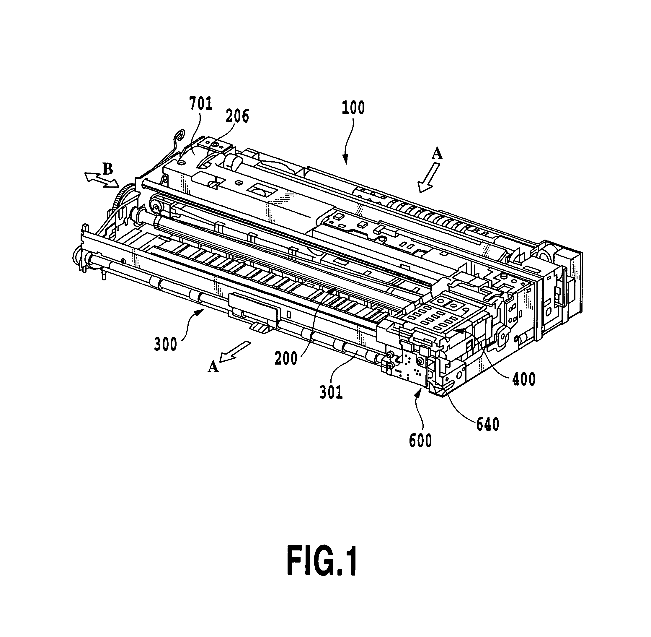
[0114]FIG. 1 is a perspective view showing an entire printing apparatus of this embodiment excluding an enclosure. A printing operation mechanism in this embodiment of the printing apparatus largely comprises an automatic paper feed unit 100, a transport unit 200, a discharge unit 300, a printing unit 400, and a recovery unit 600. The automatic paper feed unit 100 automatically feeds print sheets as print mediums to the transport unit 200 in the printing apparatus body. The transport unit 200 introduces sheets, one at a time, from the automatic paper feed unit 100 to a desired printing position and also discharges printed sheets from the printing position. The discharge unit 300 is situated downstream of the transport unit 200 in the transport direction. The printing unit 400 performs a desired printing on the sheet transported by the transport unit 200. The recovery unit 600 perfo...


PUM


Abstract

This invention provides a small and simple construction to drive a mechanism for maintaining a printing performance of a print head. In one preferred mode of the invention, a recovery device to maintain the printing performance of the print head has a suction pump unit, a capping unit and a wiping unit. The suction pump unit is driven through a spring clutch mechanism by an LF motor in the print sheet transport unit as a drive source. The capping unit and the wiping unit are driven by an AP motor as a drive source in a rotary dead zone set for a paper feed unit that feeds the print sheet to a transport unit. A piston pump is suited for use in a recovery operation to maintain the function of the print head.

Description

[0001]This application claims priority from Japanese Patent Application Nos. 2003-024917 filed Jan. 31, 2003 and 2003-024918 filed Jan. 31, 2003, which are incorporated herein by reference.BACKGROUND OF THE INVENTION[0002]1. Field of the Invention[0003]The present invention relates to a printing apparatus that uses a print head to print an image including characters on a print medium such as printing sheet as it is transported, and more particularly to a printing apparatus in which a drive source for transporting the print medium is also used as a drive source for a print head performance recovery operation for maintaining the function of the print head.[0004]The present invention also relates to a piston pump which drives a piston by a rotary drive force, and more particularly to a piston pump which is suitably applied to a recovery operation for maintaining the function of the print head in the printing apparatus demanded for size reduction and portability.[0005]2. Description of ...

Claims


Application Information

Patent Timeline
Patent Type & Authority Patents(United States)
IPC IPC(8): B41J2/165B41J2/175B41J11/00B41J23/02
CPCB41J23/025B41J2/17596
Inventor YOSHIDA, MASAHITOSHIMOYAMA, NOBORUHIRAI, YASUYUKI
Owner CANON KK
Why Eureka
Try Eureka