Catheter connector

Inactive Publication Date: 2005-09-22
CR BARD INC
View PDF99 Cites 125 Cited by
  • Summary
  • Abstract
  • Description
  • Claims
  • Application Information

AI Technical Summary

Benefits of technology

[0014] The present invention is directed to catheter connector or connection system for a subcutaneously placed catheter. The catheter connector or connection system may be configured for a single lumen catheter or a multiple lumen catheter. The catheter connector or connection system facilitates precise positioning of both distal and proximal ends of a catheter, providing enhanced functionability and patient comfort.

Problems solved by technology

Many types of catheters, however, cannot be distally trimmed due to the special configuration thereof, including, for example, dual lumen catheters with a pre-staggered tip, soft tip catheters, catheters with valved distal ends, etc.
In the case of such catheters, a pre-connected hub at the proximal end of the catheter cannot be accurately located at the venipuncture site and, consequently, some length of catheter extends therefrom.
This excess catheter length often presents difficulty in dressing the catheter and exposes the catheter to potential damage.
Moreover, it is not possible in the placement of catheters having preformed distal tips to achieve tamponade at the venipuncture site.
While such a connection system may be adequate for providing a secure connection, assembly can prove problematic due to the small size of the pieces involved as well as the extremely limited space with which the physician typically has to work.
Moreover, the manufacture of several different pieces may lengthen the time to manufacture, as well as the cost associated therewith.
Connection systems for catheters that are not designed for proximal trimming, generally also require multiple separate pieces for assembly and consequently suffer the same drawbacks described above.

Method used


Image

  • Catheter connector
  • Catheter connector
  • Catheter connector

Examples


Embodiment Construction

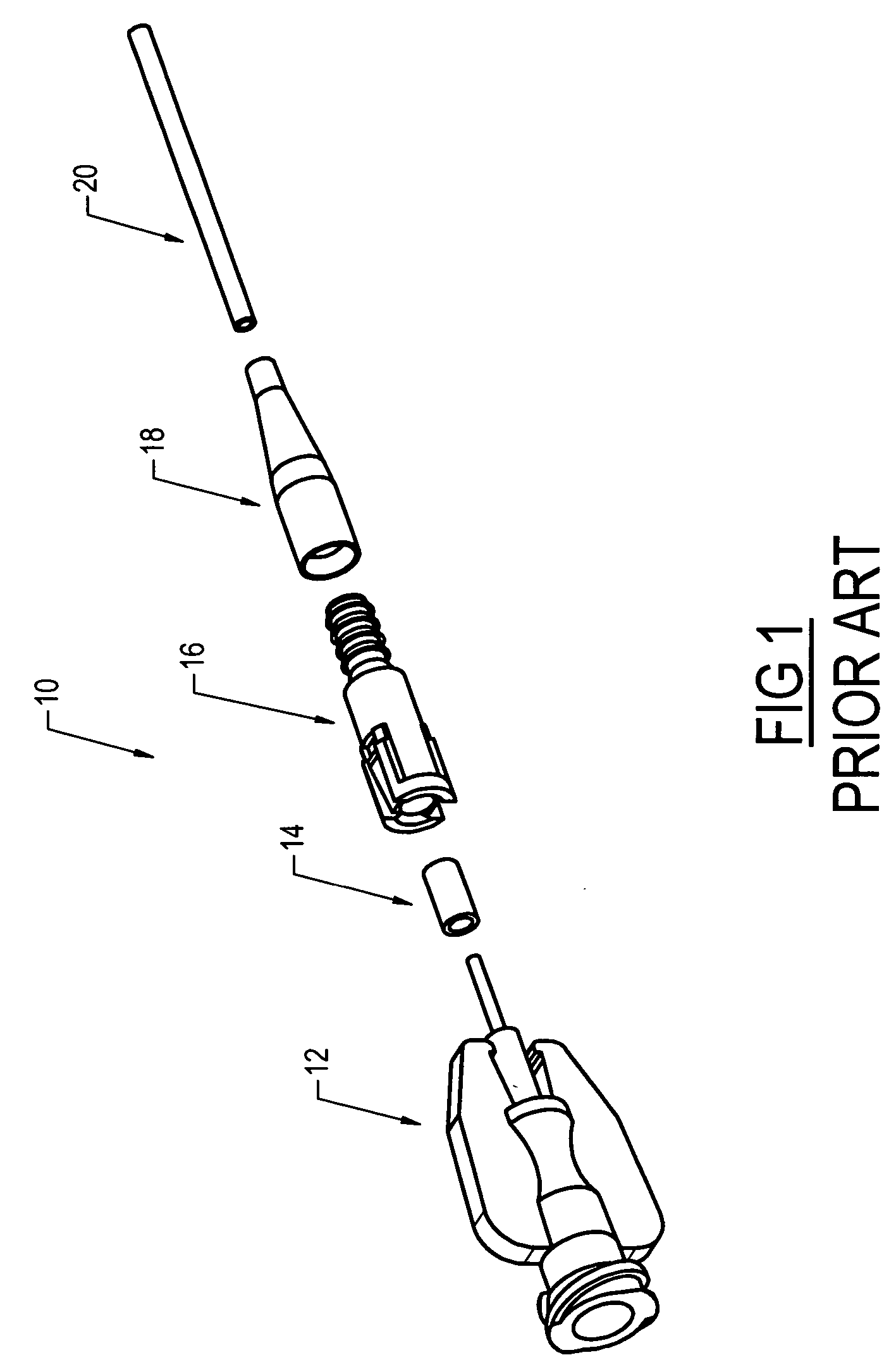
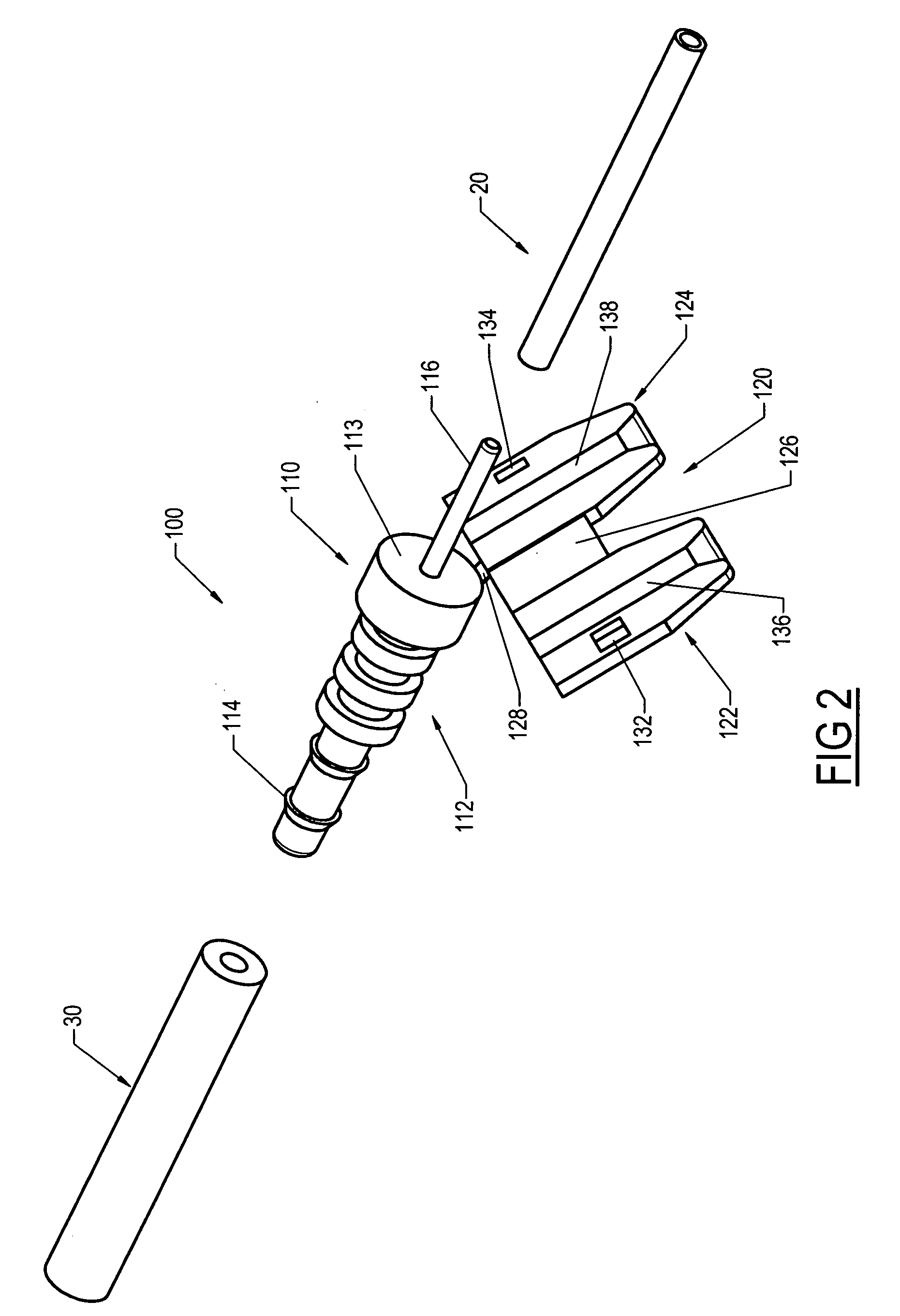
[0039] The following detailed description should be read with reference to the drawings, in which like elements in different drawings are identically numbered. The drawings, which are not necessarily to scale, depict selected preferred embodiments and are not intended to limit the scope of the invention. The detailed description illustrates by way of example, not by way of limitation, the principles of the invention. This description will clearly enable one skilled in the art to make and use the invention, and describes several embodiments, adaptations, variations, alternatives and uses of the invention, including what is presently believed to be the best mode of carrying out the invention.

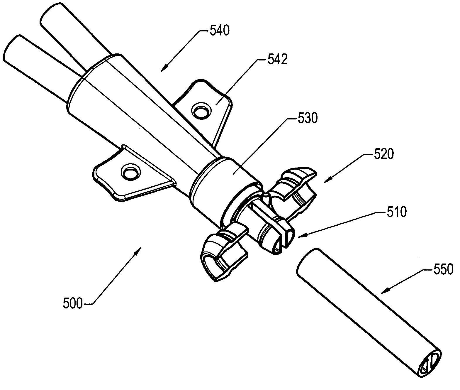
[0040] The present invention is directed to a catheter connector for connecting a catheter to extracorporeal medical equipment. In the embodiments and examples that follow, reference will be made to a catheter connector for a catheter that has been trimmed proximally, following placement thereof ...


PUM


Abstract

A catheter connector for a subcutaneously placed catheter. The catheter connector can be configured for a single lumen catheter or a multiple lumen catheter. The connector facilitates precise positioning of both distal and proximal ends of a catheter, providing enhanced functionability and patient comfort.

Description

CROSS-REFERENCE TO RELATED APPLICATIONS [0001] Not applicable. STATEMENT REGARDING FEDERALLY SPONSORED RESEARCH OR DEVELOPMENT [0002] Not applicable. REFERENCE TO A COMPACT DISK APPENDIX [0003] Not applicable. BACKGROUND OF THE INVENTION [0004] It is common to use an implanted catheter to repeatedly access the vascular system of a patient and with the catheter perform repeated therapeutic medical activity. Such therapeutic activity could include the intermittent or continuous infusion of medication and fluids, the periodic sampling of blood, or the continuous withdrawal and return of blood for processing outside of the body of the patient. The catheters used in these activities are referred to as vascular access catheters. [0005] Before any therapeutic activity can actually commence, however, the vascular access catheter must be implanted in the body of the patient with the distal tip of the catheter residing at the location in the vascular system at which an intended therapeutic ac...

Claims


Application Information

Patent Timeline
IPC IPC(8): A61M25/00A61M25/02A61M39/10A61M39/12
CPCA61M25/0097A61M39/12A61M39/1011A61M25/02Y10S604/905
Inventor BUTTS, M. DAVIDDIAMOND, JORDAN P.PATTERSON, RYANROME, GUYSTATS, JASONBARRON, WILLIAM R.
Owner CR BARD INC
Why Eureka
Try Eureka