Lane boundary detector

a detector and lane technology, applied in the field of detectors, can solve the problems of inability to provide real-time detection results, inability to satisfactorily solve time lag, and conventional lane boundary detectors cannot readily distinguish different types of lanes

Active Publication Date: 2005-09-22
TOYOTA JIDOSHA KK
View PDF13 Cites 33 Cited by
  • Summary
  • Abstract
  • Description
  • Claims
  • Application Information

AI Technical Summary

Benefits of technology

The technical effect of this patent is to create a device for detecting lanes boundaries that works well without being affected by errors or delays when identifying branches on roads. This solution should be affordable and effective.

Problems solved by technology

The technical problem addressed in this patent is the need for a lane boundary detector that can quickly and accurately detect the position of the lane boundary in real-time, without being affected by time lag or image quality. Additionally, the detector should be able to distinguish different types of lanes and be immune to detection errors, particularly when driving on highways.

Method used


Image

  • Lane boundary detector
  • Lane boundary detector
  • Lane boundary detector

Examples


first embodiment

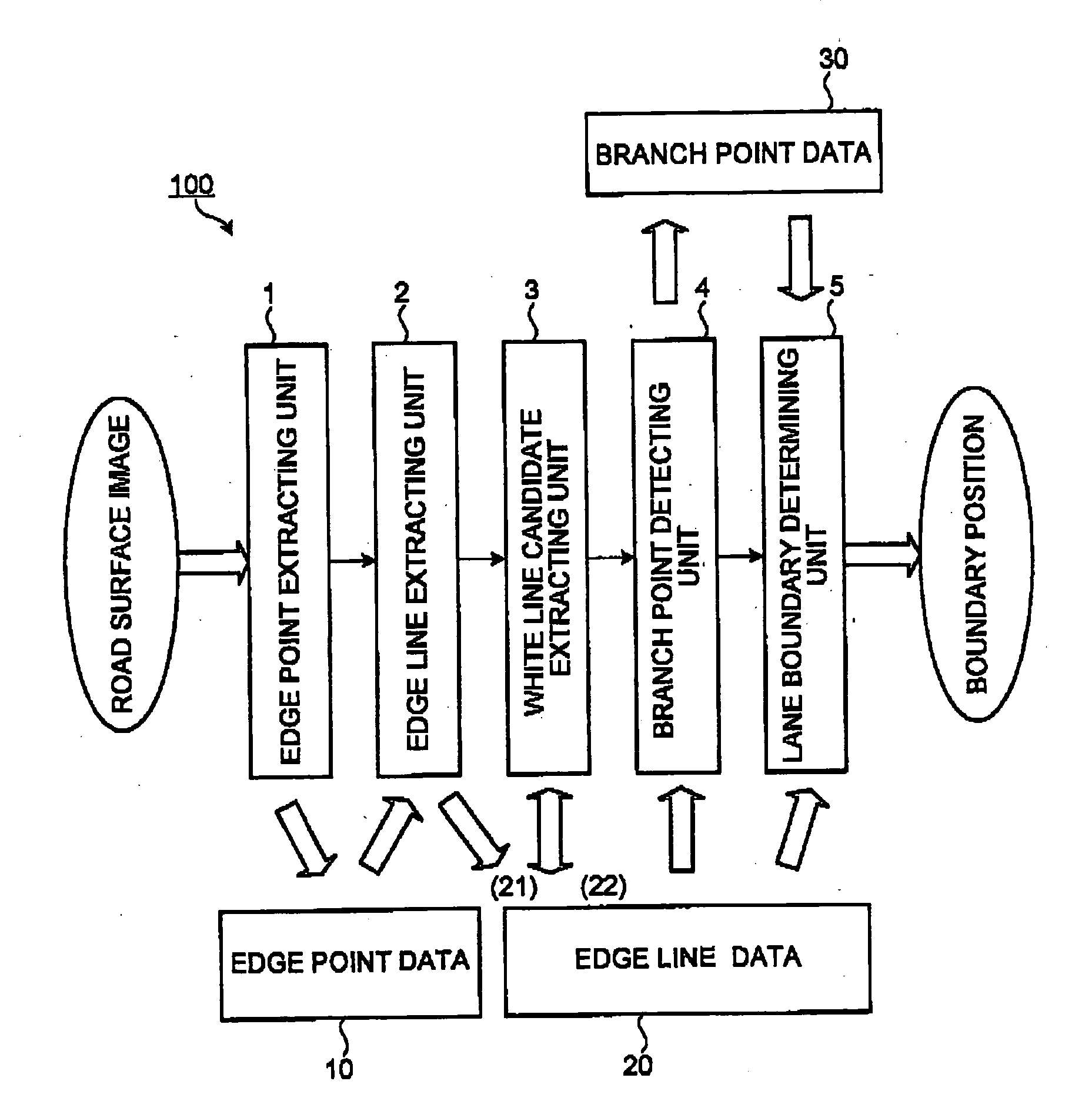
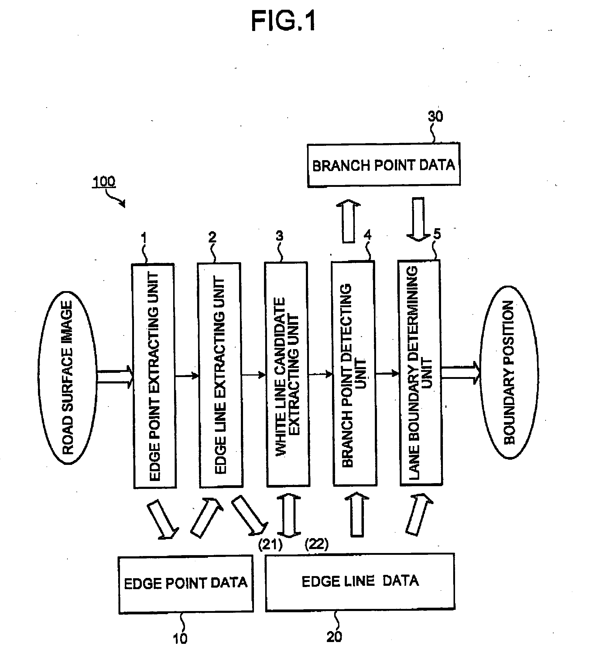
[0049]FIG. 1 shows a logical system structure of a lane boundary detector 100 according to a The edge point extracting unit 1 extracts an edge point based on a road surface image (hereinafter also referred to as image data) picked up by a vehicle-mounted camera, to store the extracted edge point as edge point data in a predetermined storage area such as a table 10. Here, the edge point is a point constituting a contour of lane sign such as a white line. The units 1 to 5 are realized with a computer system that communicates with the vehicle-mounted camera and has a known structure.

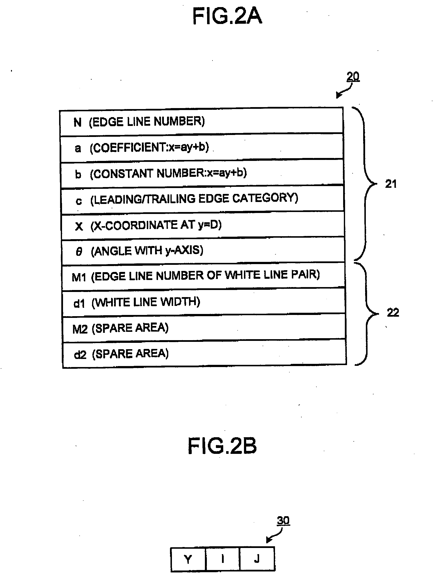
[0050] The edge line extracting unit 2 extracts an edge line which is a contour of the lane sign based on the edge point data, to store the data representing the edge line, i.e., edge line data, into a predetermined storage area such as a table 20.

[0051] The white line candidate extracting unit 3 verifies a validity of the edge line data stored in the table 20 based on predetermined properties such as a w...

second embodiment

[0111]FIG. 12 shows an example of a modification (second embodiment) of the content to be checked as shown in FIG. 9. In this example, an image dividing unit is provided to horizontally divide the input image into upper and lower areas. As the reference edge line k described above, an edge line that matches with the lane boundary position in the lower area of the horizontally divided image is employed. The image may be divided into three, four, or more areas.

[0112] When the road surface image is divided in the horizontal direction, usually the lower area image includes an image of a road surface area, at least a part of which has been the processing object in the previous control cycle. Since the road surface area has been the object of analysis in the previous cycle if the analysis results from the previous cycle are utilized, it is highly likely that more reliable determination of the lane boundary position is achieved.

[0113] Hence, even when the reference edge line k is defined ...


PUM


Abstract

A lane boundary detector includes an edge point extracting unit that extracts a plurality of edge points of a lane sign from the input image, and an edge line extracting unit that extracts a plurality of edge lines of the lane sign from the edge points to formulate a position and a direction of each of the edge lines as a straight line on the road surface, using a parameter set consisting of at least two variables. The detector further includes a branch point detecting unit that determines whether a crossing point of two of the edge lines can be a branch point of the lane, based on whether a characteristic difference vector defined with the variables with respect to the two edge lines falls within a predetermined appropriate range, and a lane boundary determining unit that determines the left and the right boundary positions of the lane.

Description


Claims


Application Information

Patent Timeline
Owner TOYOTA JIDOSHA KK
Why Eureka
Try Eureka