Acceleration clamp assist

Inactive Publication Date: 2005-09-29
NIKON CORP
View PDF13 Cites 33 Cited by
  • Summary
  • Abstract
  • Description
  • Claims
  • Application Information

AI Technical Summary

Benefits of technology

The present invention describes how to keep two objects aligned when they are being moved very quickly. It does this by using an initial low amount of pressure to hold them together and then increasing that pressure based on the speed of movement. This helps ensure that they don't become misaligned during any sudden movements.

Problems solved by technology

The technical problem addressed in this patent text is how to maintain precise alignment of parts in an optical system or other assemblies when subjected to strong acceleration forces, without causing damage or degradation of the parts being clamped together. This problem arises because clamping arrangements and frictional engagement between parts often require large clamping forces to achieve precise alignment in the mounting plane, which can lead to high levels of stress on vulnerable parts. The patent text proposes a solution to minimize the stress placed on parts while still ensuring alignment during acceleration events.

Method used


Image

  • Acceleration clamp assist
  • Acceleration clamp assist
  • Acceleration clamp assist

Examples


Embodiment Construction

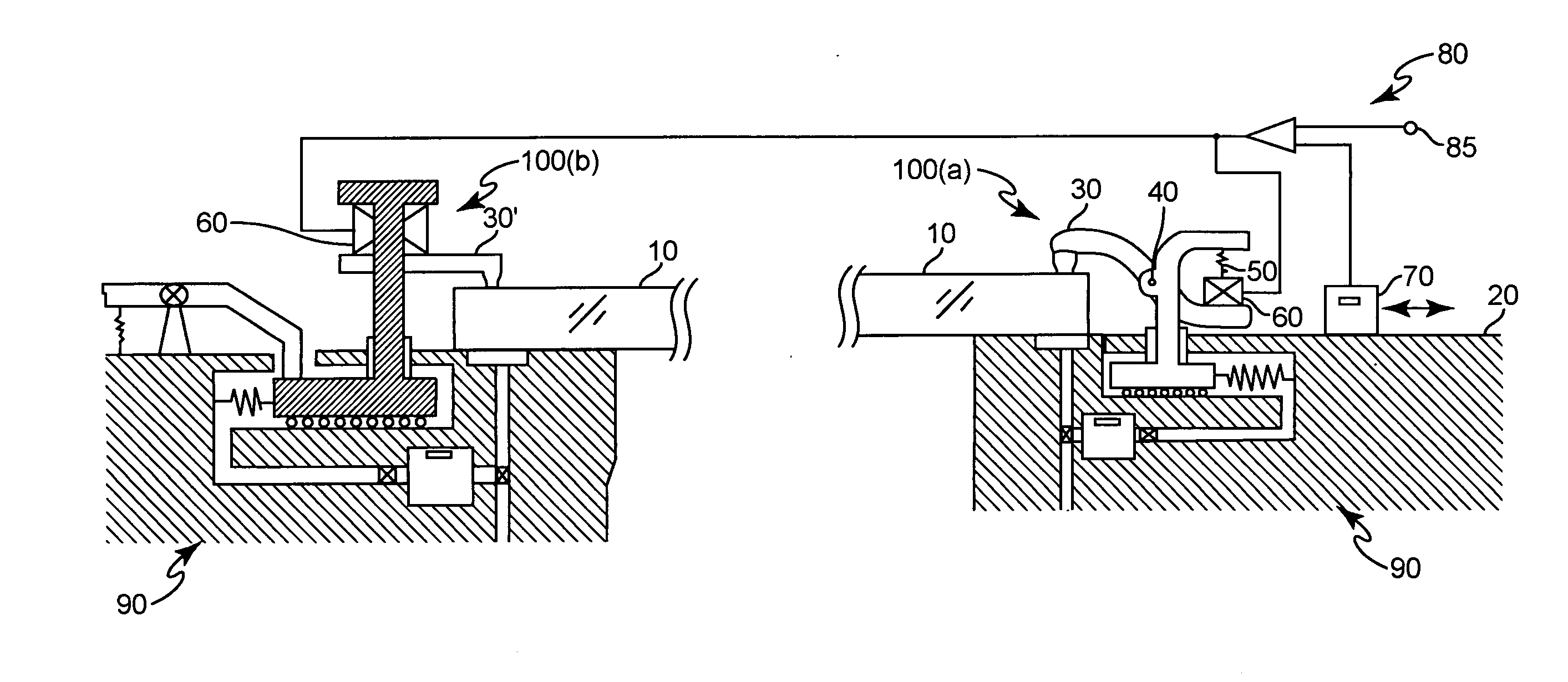
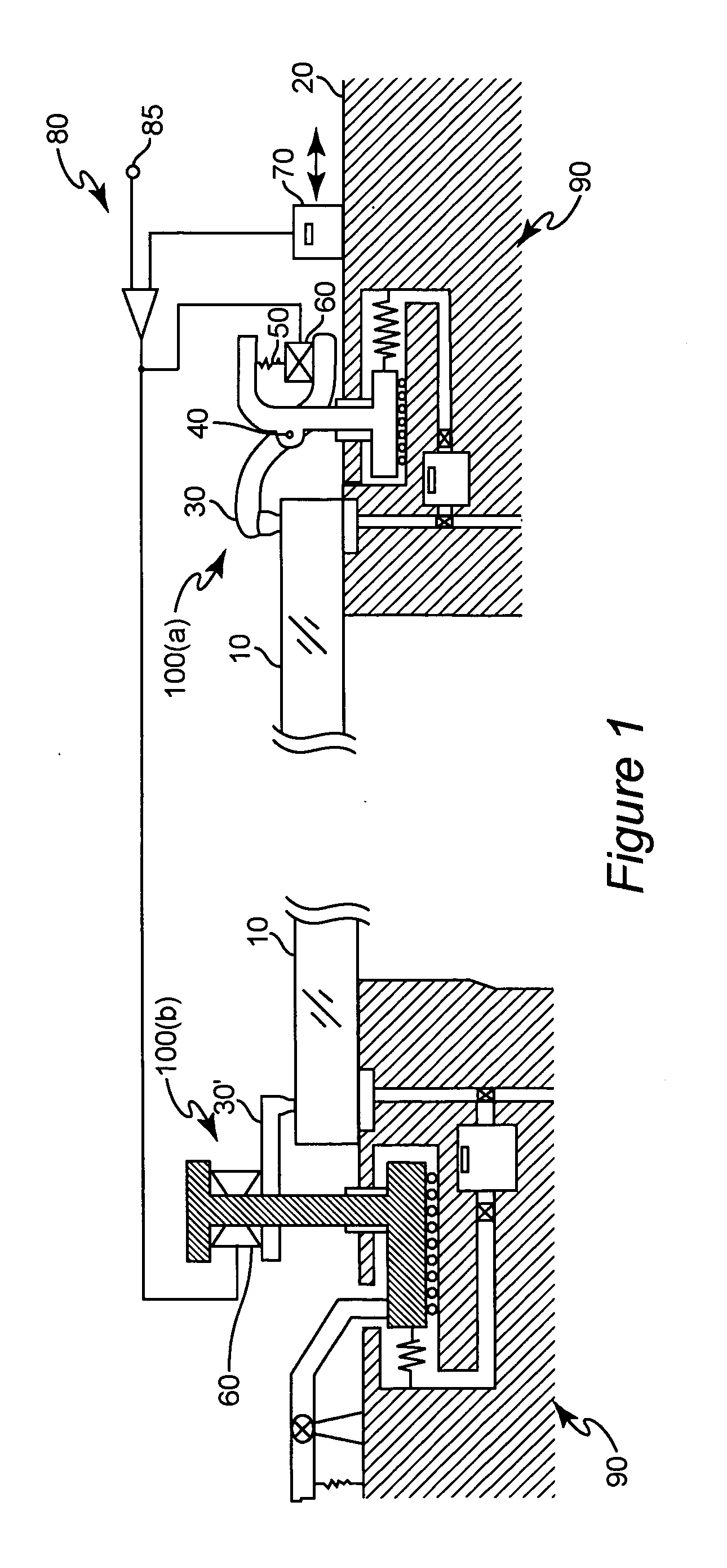
[0021] Referring now to the drawings, and more particularly to FIG. 1, there is shown in side view, a schematic depiction of a generalized form of the invention for mounting an object 10 such as a lens, mirror, reticle, mask or the like relative to (e.g. against) a surface 20 with a clamp which, for simplicity, is shown, in one form, as a lever 30 pivotally supported at pivot 40 affixed to surface 20 or, in an alternative form, as a cantilevered arm 30′. Clamp 100a and / or 100b do not have to be initially in contact with object 10. In a preferred embodiment, either clamp 100a or 100b makes contact and, in conjunction with vacuum passage 320 supplies the required cloamping force for static operation. Alternatively, vacuum passage 320 can supply the required static clamping force (e.g. slightly above the force required to maintain alignment at rest) and clamp 100a and / or 100b may provide an additional force deemed appropriate within a safety factor specification. This additional force ...


PUM


Abstract

Forces are minimized in an object supported relative to a surface by providing a first, preferably static force sufficient to retain the object is position when at rest, preferably through a clamping arrangement having a first actuator, measuring or predicting an acceleration and applying a second, preferably dynamic force corresponding to the acceleration. The first and second forces are preferably arranged to be additive or reinforcing but the arrangement can be made fail-safe at the expense of increased power consumption by arranging the first force in accordance with the maximum anticipated acceleration and counteracting the first force with the second force for lesser or zero accelerations. The second force is preferably provided by a clamp of arbitrary configuration which can be moved into and out of engagement with the object. By minimizing forces applied to the object in such a manner, damage such as creep and propagation of crystal lattice dislocations over time can largely be prevented.

Description


Claims


Application Information

Patent Timeline
Owner NIKON CORP
Why Eureka
Try Eureka