Method and Apparatus for Testing Electromagnetic Connectivity in a Drill String

a technology of electromagnetic connectivity and drill string, which is applied in the field of drill strings, can solve the problems of inability to send and receive signals to downhole, time-consuming practice costing significant amounts of money, and inability to proceed with drilling or correct connectivity

Inactive Publication Date: 2005-09-29
INTELLISERV
View PDF99 Cites 152 Cited by
  • Summary
  • Abstract
  • Description
  • Claims
  • Application Information

AI Technical Summary

Problems solved by technology

Interruptions in this electromagnetic connectivity create numerous problems.
The most immediate problem is the inability to send and receive signals to downhole, instrumented tools and bits.
However, this problem leads to

Method used


Image

  • Method and Apparatus for Testing Electromagnetic Connectivity in a Drill String
  • Method and Apparatus for Testing Electromagnetic Connectivity in a Drill String
  • Method and Apparatus for Testing Electromagnetic Connectivity in a Drill String

Examples


first embodiment

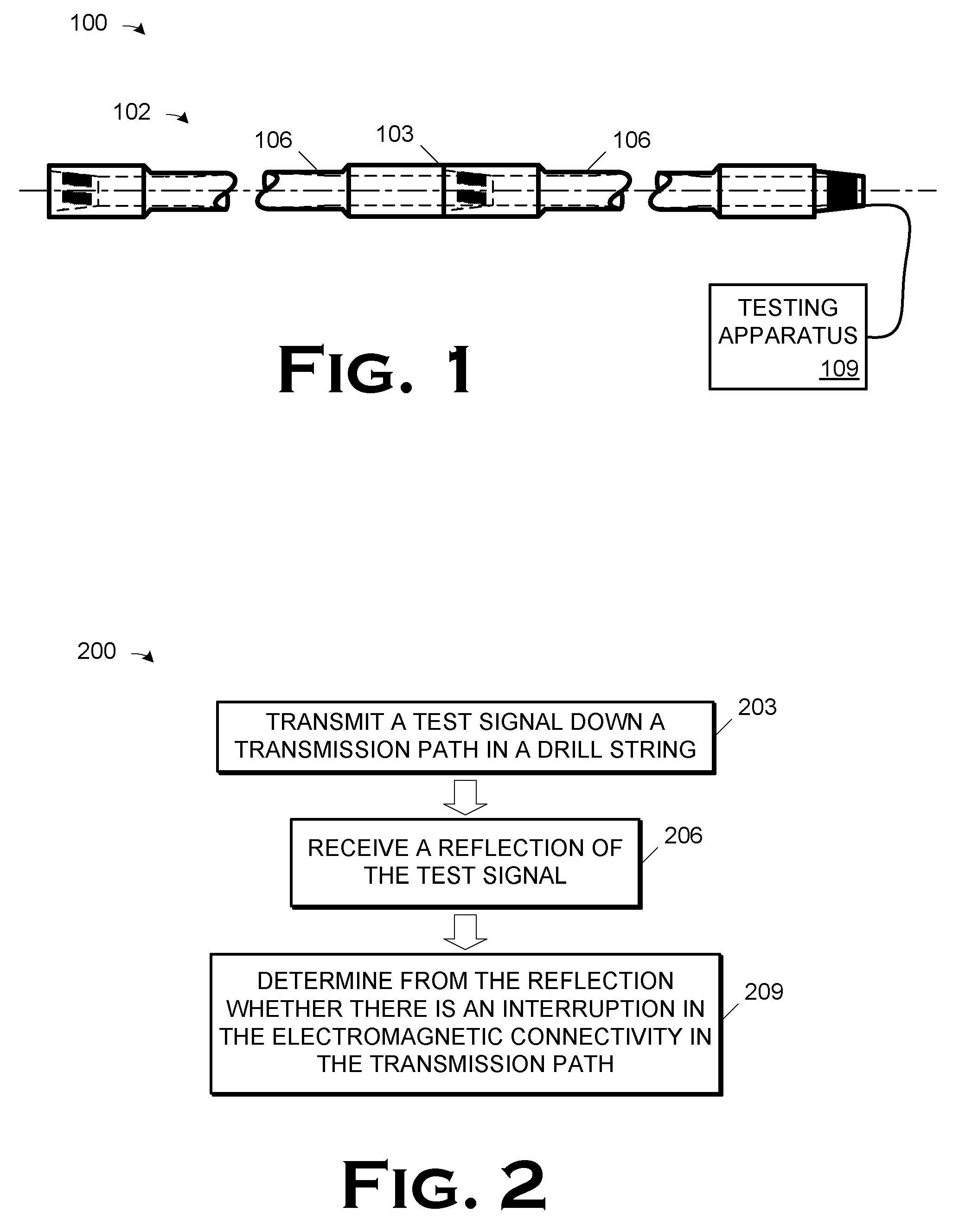
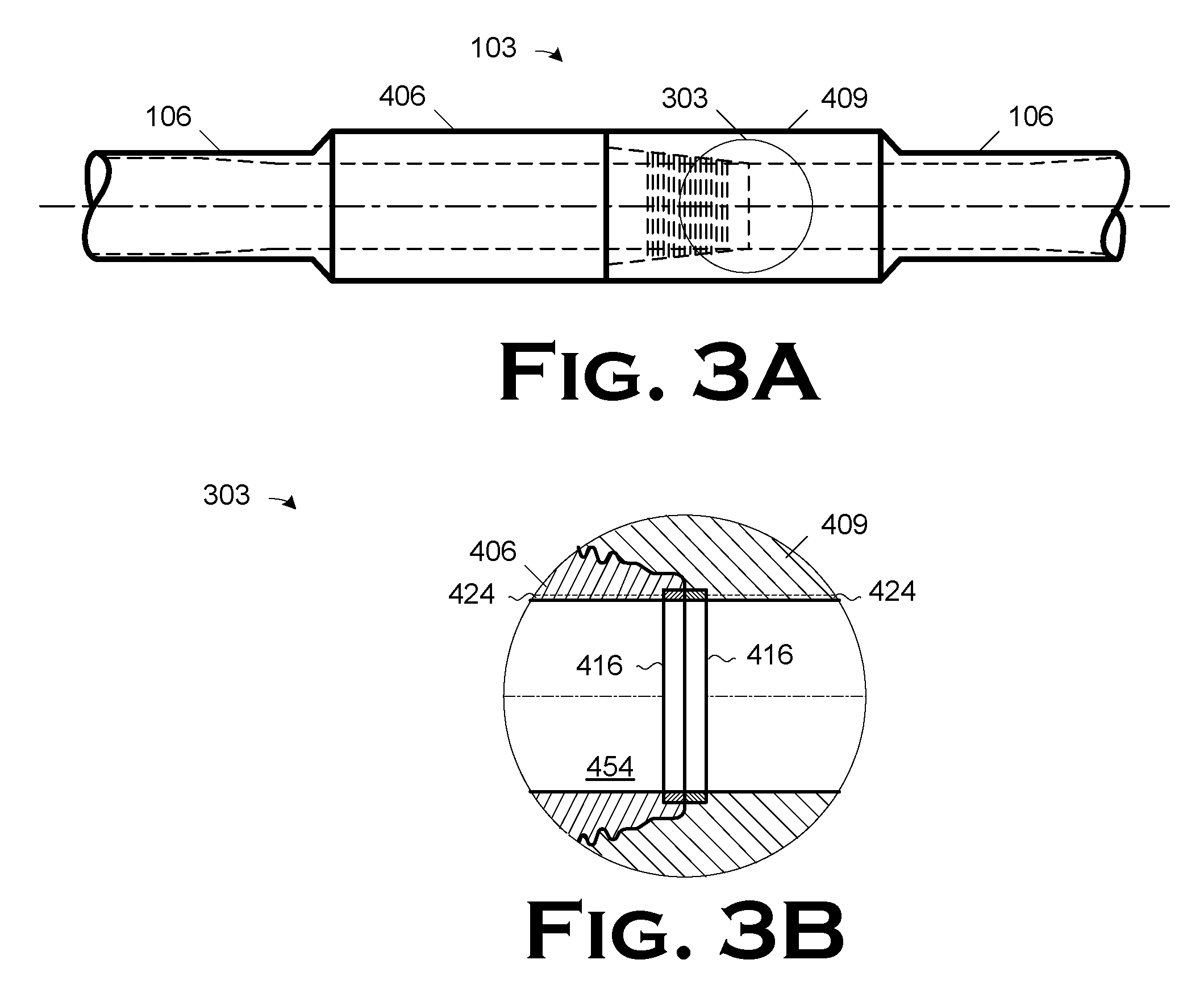
[0026]FIG. 1 illustrates an apparatus 100 with which the method of the invention may be implemented in a The apparatus 100 comprises a drill string 102 and a testing apparatus 109. The drill string includes a joint 103 comprised of two, mated sections 106 of drill pipe. Note that the number of sections 106 is not pertinent to the practice of the invention, although it may be a design consideration in some implementations. In some embodiments, the sections 106 may alternatively be tools (instrumented or not), crossovers, subs, etc. (all not shown) such as are commonly found in drill strings, or some combination of the above. In the illustrated embodiment, the joint 103 is made up in a rack (not shown) on the floor of the drilling rig before assembly into the drill string (not otherwise shown).

[0027] The drill string 102 comprises “wired pipe” that is, it includes a transmission path (not shown, but discussed further below) down its length. In accordance with the present invention, t...

embodiment 600

[0074]FIG. 7 graphs a variety of signals to illustrate how comparison can indicate whether a good connection has been made. The trace 700 is of a reflected signal indicating that a good connection has been made. Thus, the trace 700 can be, in the embodiment of FIG. 6, the reference signal Vref. FIG. 7 also includes a plurality of traces 701704 representing reflections from a shorted box end, an open box end, a shorted pin end, and an open pen end, respectively. Each of the traces 700704 represents the amplitude (in volts) of the reflected signal over time. Note that each condition generates a unique pattern in the reflection. Thus, a more sophisticated examination of the reflected signal than is performed in the embodiment 600 in FIG. 6 can reveal not only that a connection is bad, but also the nature of the bad connection.

[0075] Consider the embodiment 800, shown in FIG. 8, of the testing apparatus 109, first shown in FIG. 1. The embodiment 800 comprises a network analyzer 803, a t...

embodiment 500

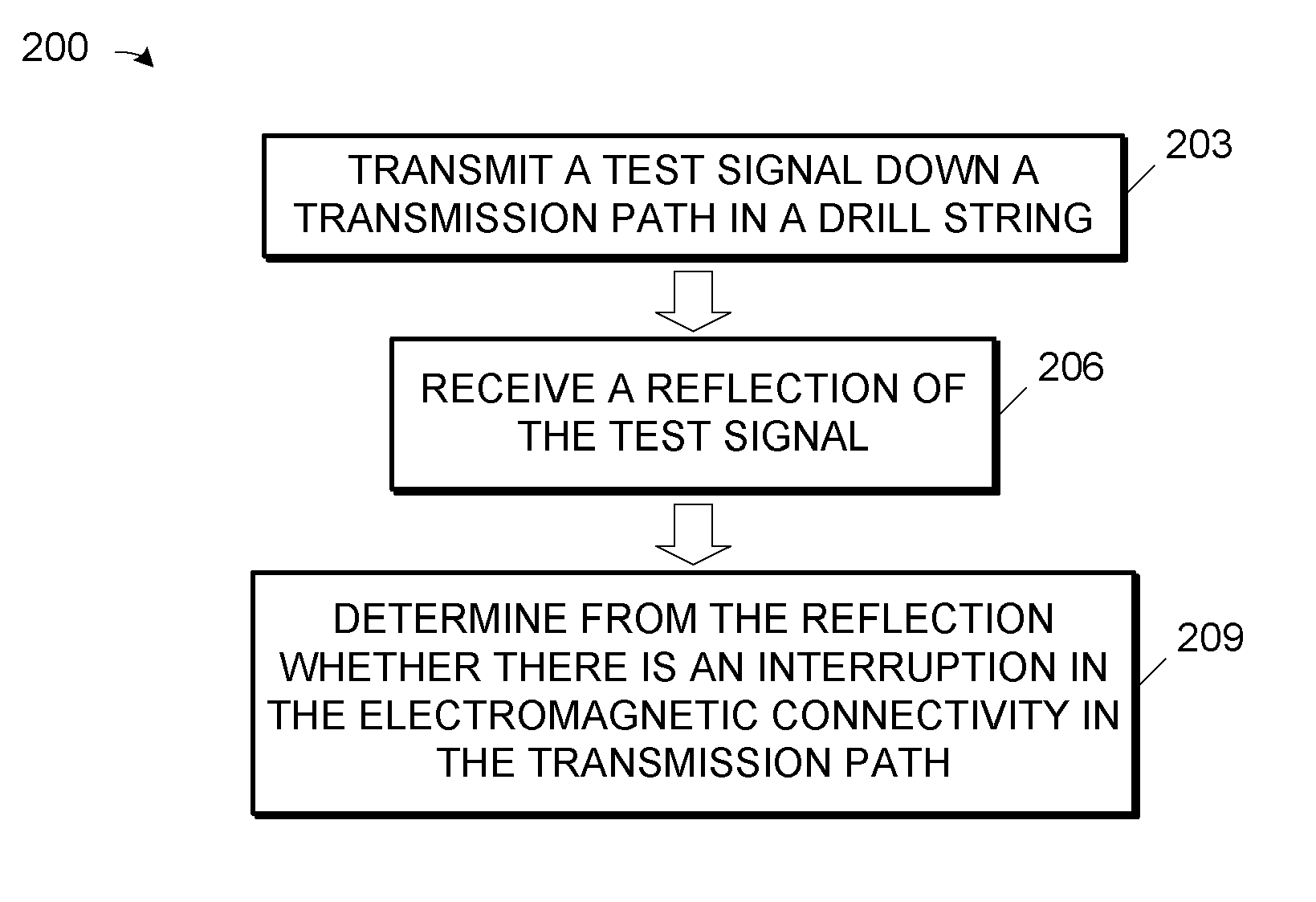
[0089] Thus, the computing apparatus 925 is programmed to facilitate determining from the reflection whether there is an interruption in the electromagnetic connectivity in the transmission path. Note, however, that the computing apparatus 925 may make the determination itself; for example, in a manner analogous to the embodiment 500 in FIG. 5A. Note also that distributing the testing apparatuses 933 throughout the drill string 903 simplifies the traces from which the determination of connectivity is made and facilitates a finer granularity in the locating a bad connection, should one exist.

[0090] Note that some portions of the detailed descriptions herein are consequently presented in terms of a software implemented process involving symbolic representations of operations on data bits within a memory in a computing system or a computing device. These descriptions and representations are the means used by those in the art to most effectively convey the substance of their work to oth...


PUM


Abstract

A method and apparatus for testing electromagnetic connectivity in a drill string are disclosed. The method includes transmitting a test signal down a transmission path in a drill string; receiving a reflection of the test signal; and determining from the reflection whether there is an interruption in the electromagnetic connectivity in the transmission path. In general, the apparatus includes a signal generator for generating a test signal into the drill string; a receiver for receiving the reflection of the test signal; and means for determining from the reflection whether there is an interruption in the electromagnetic connectivity in the transmission path. Preferably, a common coil is included through which the test signal generated by the signal generator may be transmitted into a drill string and through which a reflection of the test signal may be received.

Description

FEDERAL RESEARCH STATEMENT [0001] This invention was made with government support under Contract No. DE-FC26-97FT343656 awarded by the U.S. Department of Energy. The government has certain rights in the invention.BACKGROUND OF INVENTION [0002] 1. Field of the Invention [0003] The present invention pertains to drill strings, and, more particularly, to a method and apparatus for testing electromagnetic connectivity in a drill string. [0004] 2. Description of the Related Art [0005] Drilling operations, especially to establish production of hydrocarbon deposits, frequently employ relatively long drill strings terminated by a bit. The drill string is usually fed through the floor of a drilling rig. As the bit bores through the earth, additional sections of drill pipe, tools, etc. are made up and become a portion of the drill string. The drill string may eventually reach as long as 20,000″ 30,000″, or even longer. [0006] As the industry evolves, obtaining information downhole regarding th...

Claims


Application Information

Patent Timeline
IPC IPC(8): E21B47/12G01R27/04G01R31/02
CPCG01R31/026E21B47/122G01R31/54G01R31/52E21B47/13
Inventor HALL, DAVID R.HALL, H. TRACY JR.PIXTON, DAVID S.RAWLE, MICHAELBARTHOLOMEW, DAVID B.SOARES, MARSHALL A.
Owner INTELLISERV
Why Eureka
Try Eureka