Integrated internal power supply

a power supply and internal technology, applied in the direction of electrical apparatus casings/cabinets/drawers, emergency protection arrangement details, cooling/ventilation/heating modifications, etc., can solve the problems of limiting the involvement of the user in the design of the power supply, the consumption of floor space or wall-outlet space by the external power supply, and the inability of the end user to control the power supply. the effect of enhancing the capability of the power supply function

Inactive Publication Date: 2005-09-29
PATTON ELECTRONICS
View PDF7 Cites 12 Cited by
  • Summary
  • Abstract
  • Description
  • Claims
  • Application Information

AI Technical Summary

Benefits of technology

[0016] The invention having provided the benefits of modularity and integration in the provision of power, the invention also provides a platform for supplemental functions. These functions can enhance the capability of the power supply function or they can provide to the end-use equipment additional functions not directly related to the power supply function, but that also benefits the end-use equipment on account of the same principles of modularity, integration and cost reduction. Examples of integrated functions that enhance the capability of the power supply function are a.) current sharing circuitry, b.) voltage adjustment circuitry, c) remote voltage sensing and adjusting circuitry, d) output diode OR'ing circuitry, e) a voltage measurement device, f) a power quality measurement device, g) a “shutdown” input, h) a “power fail” output, l) an overvoltage protection circuit, j) an undervoltage lockout circuit, k) a current limit circuit, l) a battery managemen

Problems solved by technology

The designer of the end-use equipment can therefore limit his involvement in power supply design to the selection of an external power supply.
However, external power supplies have some deficiencies.
End-users also do not like the consumption of floor-space or wall-outlet space consumed by an external power supply, compared to the simple power cord of end-use equipment having an integral power supply.
They also tend to question the quality of an external power supply and question the effectiveness of the vendor quality control exercis

Method used


Image

  • Integrated internal power supply
  • Integrated internal power supply
  • Integrated internal power supply

Examples


Embodiment Construction

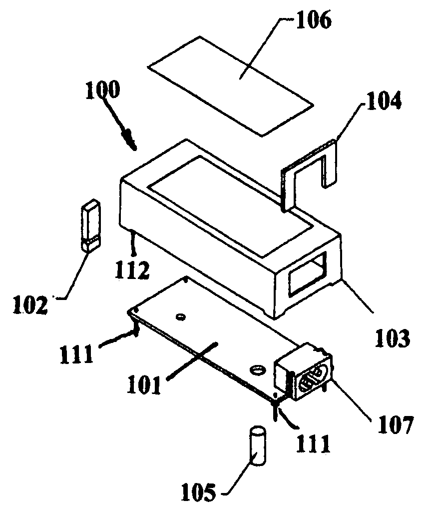
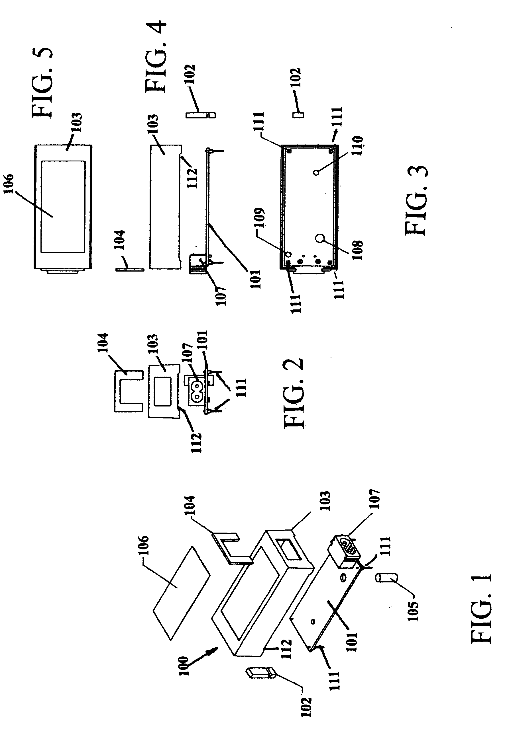
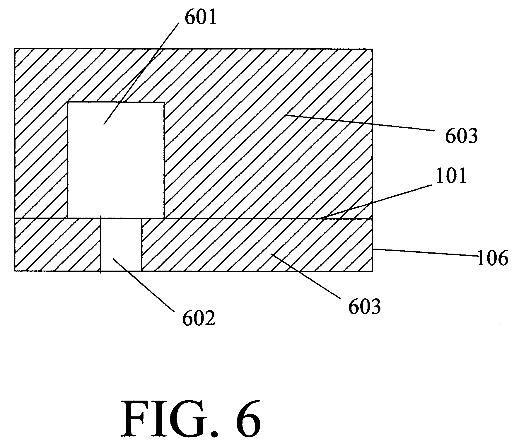
[0026] In a preferred embodiment shown in the figures, an integrated internal power supply 100 according to the invention includes a printed circuit board 101 with an integral power connector 107 arranged so as to protrude through the wall of an equipment enclosure (not shown) when the power supply is mounted therein, as well as a board holder 102, a case 103 with a label 106, a clip 104, and a plug 105. Board 101 is also provided with a vent hole 108, potting fill holes 109 and 110, and pins 111. Vent hole 108 is provided to allow gasses and / or electrolyte to be vented from a capacitor employed in the power supply, such as a large electrolytic smoothing capacitor. Case 103 is preferably provided with steps or notches 112, to position the printed circuit board within the enclosure during the application and curing of the potting material. This ensures that the potting material covers the components.

[0027] In another embodiment of the invention, as shown in FIG. 7, grooves 702 provi...


PUM


Abstract

Integrated internal power supply with a power inlet connector arranged to protrude through a housing of an end-use equipment, and having internal circuitry potted in a thermally conducting material. A vent path is provided so that a component such as a large capacity electrolytic capacitor can vent surplus fluid, e.g. electrolyte and/or gas. The power supply has a standardized ‘footprint’ and may be mounted directly onto a circuit board in the end-use equipment. The supply is preferably assembled by mounting a board holder on an internal circuit board, mounting a clip on the power inlet connector, mounting the internal circuit board in a case, plugging a vent hole in the internal circuit board, filling the case with potting compound, baking the power supply, preferably at 100° C. for 10 minutes, and then unplugging the vent hole.

Description

BACKGROUND OF THE INVENTION [0001] 1. Field of the Invention [0002] The invention relates to an integrated internal power supply. More particularly, the invention relates to a power supply having a vent for exhausting gasses or electrolyte from a capacitor, and a method of manufacture therefor. [0003] 2. Discussion of the Background [0004] Familiar external wall-mount and table-top power supplies bear several characteristics that make them valuable and attractive. They are designed, marked and “listed” in compliance with accepted safety standards (typically IEC950 / UL60950 / EN60950 for IT communication equipment). The output voltages of such external power supplies are normally “Safety Extra Low Voltage” (SFLV), thus isolating the end-use equipment from hazardous voltages. External power supplies are self-contained, having a power inlet that is integral to the external power supply. They are also integral, having power inlet, fusing, noise suppression and all power conversion circuitr...

Claims


Application Information

Patent Timeline
IPC IPC(8): H02H1/00H05K5/00
CPCH05K5/0091
Inventor MARTIN, MICHAELDUBOIS, BRYAN E.MAURER, KENNETH
Owner PATTON ELECTRONICS
Why Eureka
Try Eureka