Method of visualizing proteins bound to protein-binding membranes

a protein and membrane technology, applied in the field of detection/visualization of proteins bound to a protein-binding membrane, can solve the problems of nylon membranes that are incompatible with stains such as amido black 10b and coomassie blue, and low sensitivity of stains

Inactive Publication Date: 2005-09-29
TEMPLE UNIVERSITY
View PDF9 Cites 4 Cited by
  • Summary
  • Abstract
  • Description
  • Claims
  • Application Information

AI Technical Summary

Problems solved by technology

However these stains are characterized by low sensitivity, having a detection limit of about 50-100 ng of protein.
In particular, nylon membranes are incompatible with these stains because reactivity of the membrane itself generates a high staining background (Pluskal et al., Biotechniques, 4: 272-282, 1986).
In addition, amido black 10b and coomassie blue, though often used for their ease of removal, are not easily removed from PVDF membranes.
An additional membrane limitation is that nitrocellulose membranes cannot be used in some staining procedures because of incompatibility with high concentrations of organic solvents such as methanol.
Such harsh conditions often degrade the analyte proteins and thus preclude additional characterization that requires retention of the intact tertiary protein structure.
Thus, in current practice, staining procedures for proteins often involve reagent profiles that are undesirable for reasons including: low sensitivity; lengthy incubation time; reagents that denature or otherwise degrade the analyte proteins precluding further characterization such as immunodetection; and incompatibility with certain protein-binding membrane compositions.

Method used


Image

  • Method of visualizing proteins bound to protein-binding membranes
  • Method of visualizing proteins bound to protein-binding membranes
  • Method of visualizing proteins bound to protein-binding membranes

Examples


example 1

Comparison of Different Staining Methods

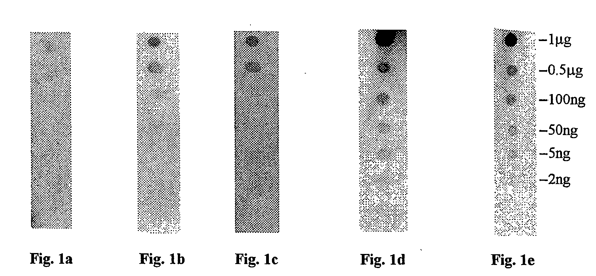
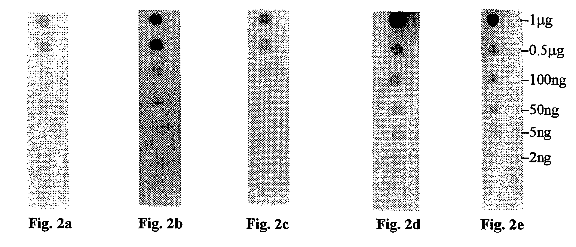
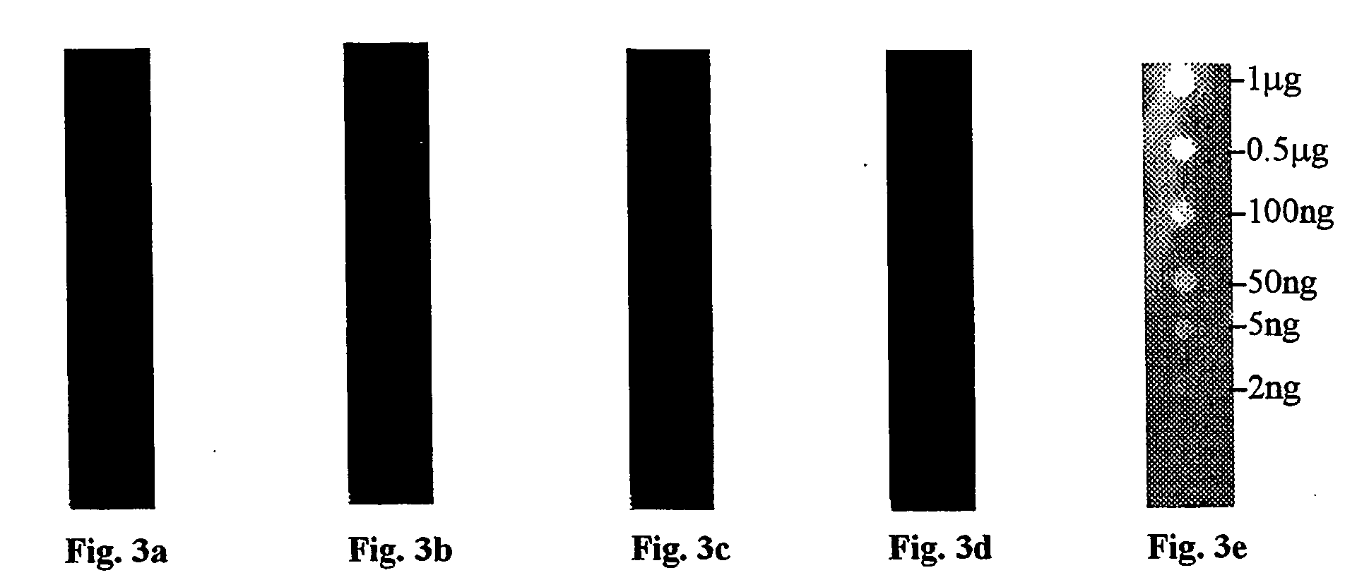
[0106] Membranes of three types (PVDF, nitrocellulose, and nylon) were prepared by cutting into strips (1 cm×8 cm). Each of the membrane strips were spotted with 1 μL spots of bovine serum albumin (BSA) in a series of amounts comprising: 2 ng, 5 ng, 50 ng, 10 ng, 500 ng and 1000 ng of protein. Due to the hydrophobic nature of the PVDF membrane, the protein solution for spotting of the PVDF membrane was mixed with an equal volume of caprolactone before spotting.

[0107] Each membrane of each composition was then stained with one of a group of five staining compositions selected as follows:

[0108] One membrane of each composition was stained using ponceau S. In this procedure, the membrane was incubated in solution with a concentration of 0.1% (w / v) of ponceau S stain in 5% acetic acid for 5 min. The stain was then decanted and the membrane washed with deionized water until the background was removed leaving only the detected protein. The membra...

example 2

Quantitation of Proteins Using Reactive Brown 10

[0116] 1 μL of an unknown protein solution is spotted on a PVDF membrane. 1 μL of each of a series of standard, known concentration solutions of bovine serum albumin, in a range from 2 ng / μL to 20 ng / μL, were spotted on different locations on the same membrane. All of the protein spots were stained with a 0.1% solution of reactive brown 10 in water for approximately one minute. This step was followed by destaining by incubating in water for about one minute. Following the destaining of the membrane, the protein spot were scanned using a Hewlett Packard ScanJet IIcx. The scanned images were then analyzed using a Molecular Dynamics personal Densitometer.

[0117] A standard calibration curve was generated (FIG. 4) and used to determine the concentration of the unknown protein.


PUM

PropertyMeasurementUnit
thicknessaaaaaaaaaa
timeaaaaaaaaaa
pHaaaaaaaaaa

Abstract

A method of visualizing proteins bound to a protein-binding membrane is provided herein, comprising reacting proteins bound to protein-binding membranes with a compound of formula (I) wherein Ra, R1, R2, R3, R4, M, n, and m are as defined herein.

Description

FIELD OF THE INVENTION [0001] The present invention relates to the detection / visualization of proteins bound to a protein-binding membrane using staining reagents defined herein. BACKGROUND OF THE INVENTION [0002] Protein analyses often begin with electrophoretic separation of a mixture of proteins. In a typical application, proteins migrate through a gel under the influence of an electric field. The rate of migration is dependent on the charge, size and shape of the protein. When the separation is complete, blots, on protein-binding membranes are made from the gels on which the electrophoretic separation is performed. [0003] The general techniques for protein separation and for blotting onto a protein-binding membrane are well known (Techniques in Molecular Microbiology, J. Walker and W. Gaastre (Eds); G. Bers and D. Garfin, Bio Techniques, Vol. 3, No. 4, pp. 276-288 (1985)). [0004]“Protein blotting” is a term that refers to the transfer of electrophoretically-resolved protein samp...

Claims


Application Information

Patent Timeline
Patent Type & Authority Applications(United States)
IPC IPC(8): B01D15/04C09B62/018C09B62/767C12N1/00C12Q1/00G01NG01N33/00G01N33/68
CPCG01N33/683
Inventor YONAN, CHRISTOPHER R.CHANG, FRANK N.
Owner TEMPLE UNIVERSITY
Why Eureka
Try Eureka