Rotary actuator

Active Publication Date: 2005-09-29
DENSO CORP
View PDF9 Cites 28 Cited by
  • Summary
  • Abstract
  • Description
  • Claims
  • Application Information

AI Technical Summary

Benefits of technology

[0016] In view of the above-described problems, the present invention has an object to provide a

Problems solved by technology

The radial inner portion of the rotor core, where the rotor core and the rotor shaft are connected, has an electromagnetically excessive capacity.
In general, if the sun gear inclines or tilts, there will be the possibi

Method used


Image

  • Rotary actuator
  • Rotary actuator
  • Rotary actuator

Examples


embodiment

Preferred Embodiment

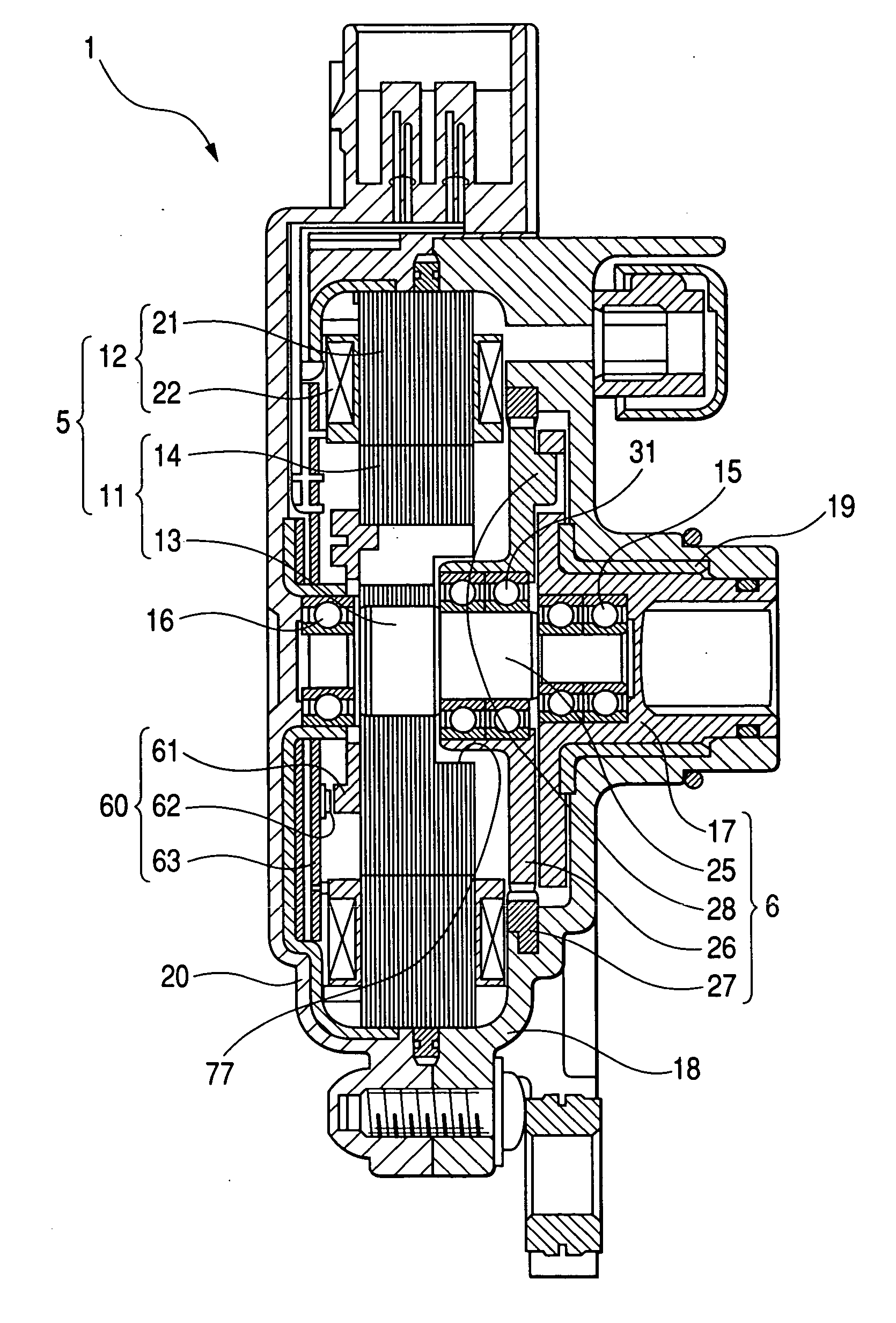
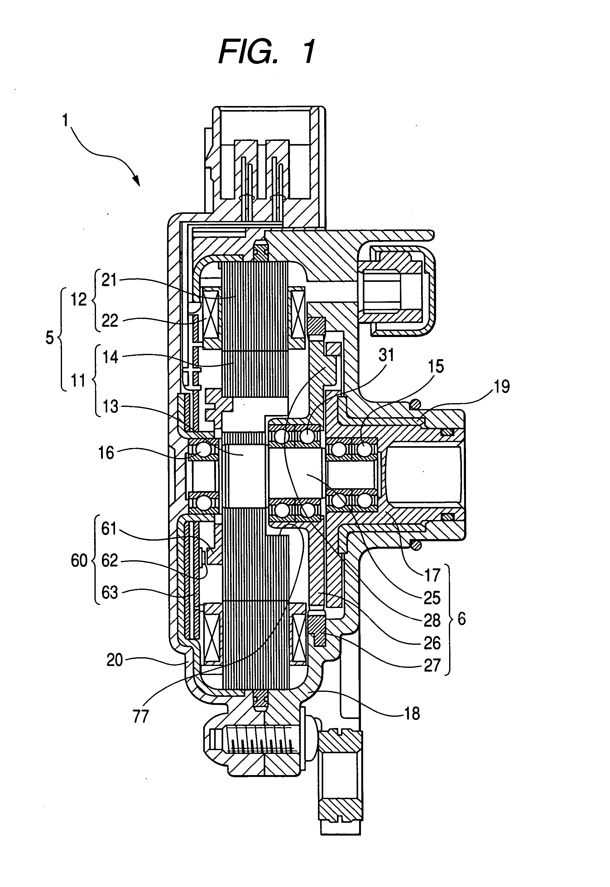
[0046] A rotary actuator in accordance with a preferred embodiment of the present invention will be explained with reference to FIGS. 1 to 14. The rotary actuator of this embodiment is for generating a driving force to control a shift-range switching apparatus of an automotive automatic transmission. First of all, the shift-range switching apparatus of the preferred embodiment will be explained.

Shift-Range Switching Apparatus

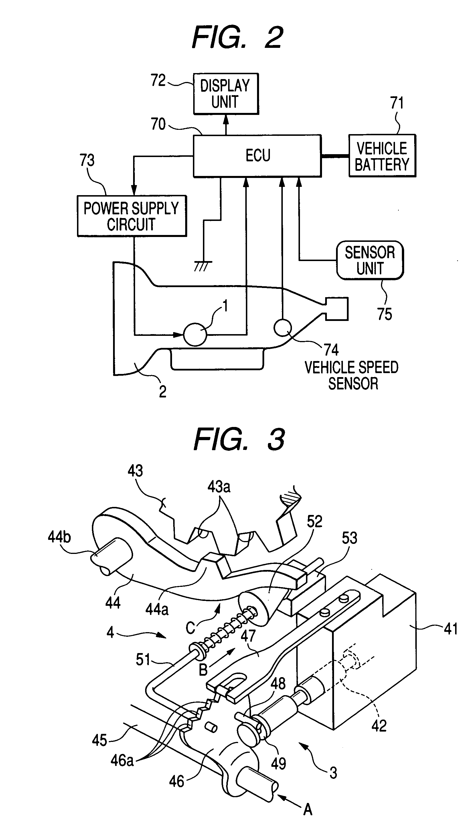
[0047] The shift-range switching apparatus is for switching a shift-range switching mechanism 3 (including a parking lock / unlock mechanism 4: refer to FIG. 3) mounted on an automotive automatic transmission 2 (refer to FIG. 2) with the aid of a rotary actuator 1 (refer to FIG. 1). The rotary actuator 1, capable of acting as a servo mechanism for driving the shift-range switching mechanism 3, includes a synchronous motor 5 and a reduction gear unit 6. The rotary actuator 1 shown in FIG. 1 has a front part facing rightward and a rear part pos...


PUM


Abstract

A radial inner portion of a rotor core, where a rotor core and a rotor shaft are connected, has an electromagnetically excessive capacity. A recess is provided at the radial inner portion of the rotor core. The recess is a cylindrical bore retracting in the axial direction from the front surface of the rotor core, facing to a reduction gear unit, toward the rear surface of the rotor core. A sun gear bearing, supporting a sun gear of the reduction gear unit, is disposed at least partly in the recess. Extending the sun gear bearing in the axial direction brings the effects of preventing inclination of the sun gear, improving transmission efficiency of the reduction gear unit, and producing a large output torque without increasing the overall size.

Description

CROSS-REFERENCE TO RELATED APPLICATION [0001] This application is based upon and claims the benefit of priority from earlier Japanese Patent Application No. 2004-93157 filed on Mar. 26, 2004 so that the description of which is incorporated herein by reference. BACKGROUND OF THE INVENTION [0002] The present invention relates to a rotary actuator including a combination of a motor and a reduction gear unit, and more particularly to a rotary actuator including a motor and a reduction gear unit disposed adjacently in the axial direction to realize a compact and slim structure. The Japanese patent application Laid-open No. 2004-69021 discloses a conventional rotary actuator including a motor and a reduction gear unit disposed adjacently in the axial direction. [0003] In general, improvement of output torque in the rotary actuator will be realized: [0004] (1) when the motor size is enlarged; [0005] (2) when the motor winding is enhanced (i.e. the ampere-turn is increased); [0006] (3) when...

Claims


Application Information

Patent Timeline
IPC IPC(8): F16H48/06F16H1/32F16H59/08F16H61/32H02K7/08H02K7/116
CPCF16H1/32F16H59/08F16H2061/326H02K7/116H02K7/083
Inventor KIMURA, KIYOSHIITOH, TAKUYOSHIYAMA, SHIGERU
Owner DENSO CORP
Why Eureka
Try Eureka