Constant temperature controller

a constant temperature controller and controller technology, applied in the direction of domestic cooling devices, lighting and heating devices, machines' operation modes, etc., can solve the problems of inability to precisely predict when the heat load that has been changed returns the heat load that has been changed may not always return from the external heat load apparatus, so as to quickly react to the fluctuation of the lead load, the operation status can be quickly stabilized, and the fluctuation of the temperature difference can be detected quickly.

Inactive Publication Date: 2006-10-12
ATS
View PDF0 Cites 19 Cited by
  • Summary
  • Abstract
  • Description
  • Claims
  • Application Information

AI Technical Summary

Benefits of technology

[0034] The constant temperature controller according to the present invention includes the cooler operation mode switch that selects the cooler operation mode based on the difference between the circulating fluid temperature at the inlet port of the cooler and the circulating fluid temperature at the outlet port of the heater. Such configuration allows quickly detecting the fluctuation in the difference in temperature of the constant temperature controller even during the transition of the target temperature, to thereby quickly react the fluctuation of the lead load, thus allowing switching the operation mode under a stabilized situation without overshooting or undershooting the target temperature by far. As a result, the operation mode can be timely switched and therefore the operation status can be quickly stabilized.
[0035] The constant temperature controller according to the present invention includes the cooling power controller that adjusts the cooling power by the inverter frequency that drives the compressor in the refrigerator cycle, and is therefore capable of switching the cooler operation mode between the idling mode and the loaded mode, and thereby performing the energy-saving operation.
[0036] The constant temperature controller according to the present invention includes the cooling power controller that adjusts the cooling power by controlling the aperture of the electronic expansion valve provided in the refrigerator cycle, which enables quickly changing the temperature under the loaded mode, as well as performing extremely accurate temperature control of the cooler.
[0037] The constant temperature controller according to the present invention includes the cooling power controller that adjusts the cooling power of the cooler such that the difference between the circulating fluid temperature at the outlet port of the cooler and the target temperature of the heater becomes a predetermined target difference in temperature. Such configuration enables maintaining the temperature of the circulating fluid flowing into the heater at a generally constant level, and setting the target difference in temperature in a small range can reduce the influence of the fluctuation of the heat load returning from the external heat load apparatus, which permits selecting a heater of a quite small output, such as an electric heater, yet controlling the circulating fluid temperature flowing out of the heater, quite accurately and at real time.
[0038] The constant temperature controller according to the present invention includes the temperature control function of dividing the temperature range of the circulating fluid at the outlet port of the cooler into a plurality of predetermined temperature zones, and utilizing the electronic expansion valve that controls the cooling power of the cooler according to the respective temperature zones. Such method grants a reasonable margin to the temperature based on which the aperture of the electronic expansion valve is to be controlled, thereby improving the stability of the temperature.
[0039] The constant temperature controller according to the present invention employs the heater with the PID feedback control function, which allows employing a small-sized electric heater thus to perform the energy-saving operation, as well as accurately controlling the temperature of the circulating fluid supplied to the external heat load apparatus.

Problems solved by technology

It is impossible to precisely foresee when the heat load that has been changed returns from the external heat load apparatus, i.e. the object of the temperature control.
Although the target temperature of the constant temperature controller is changed, the heat load that has been changed may not always return from the external heat load apparatus after the temperature of the heat medium fluid at the outlet port of the constant temperature controller has reached the newly set target and has been stabilized.

Method used


Image

  • Constant temperature controller
  • Constant temperature controller
  • Constant temperature controller

Examples


first embodiment

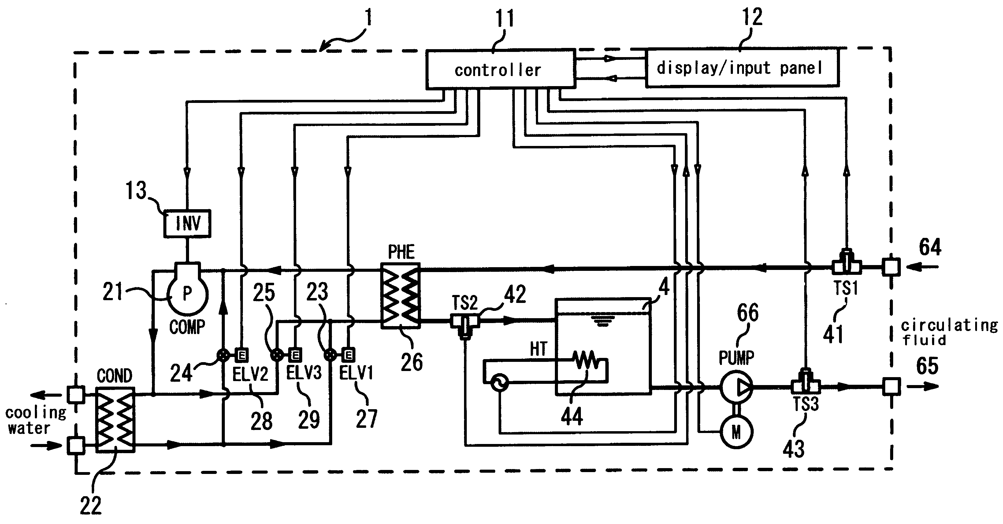
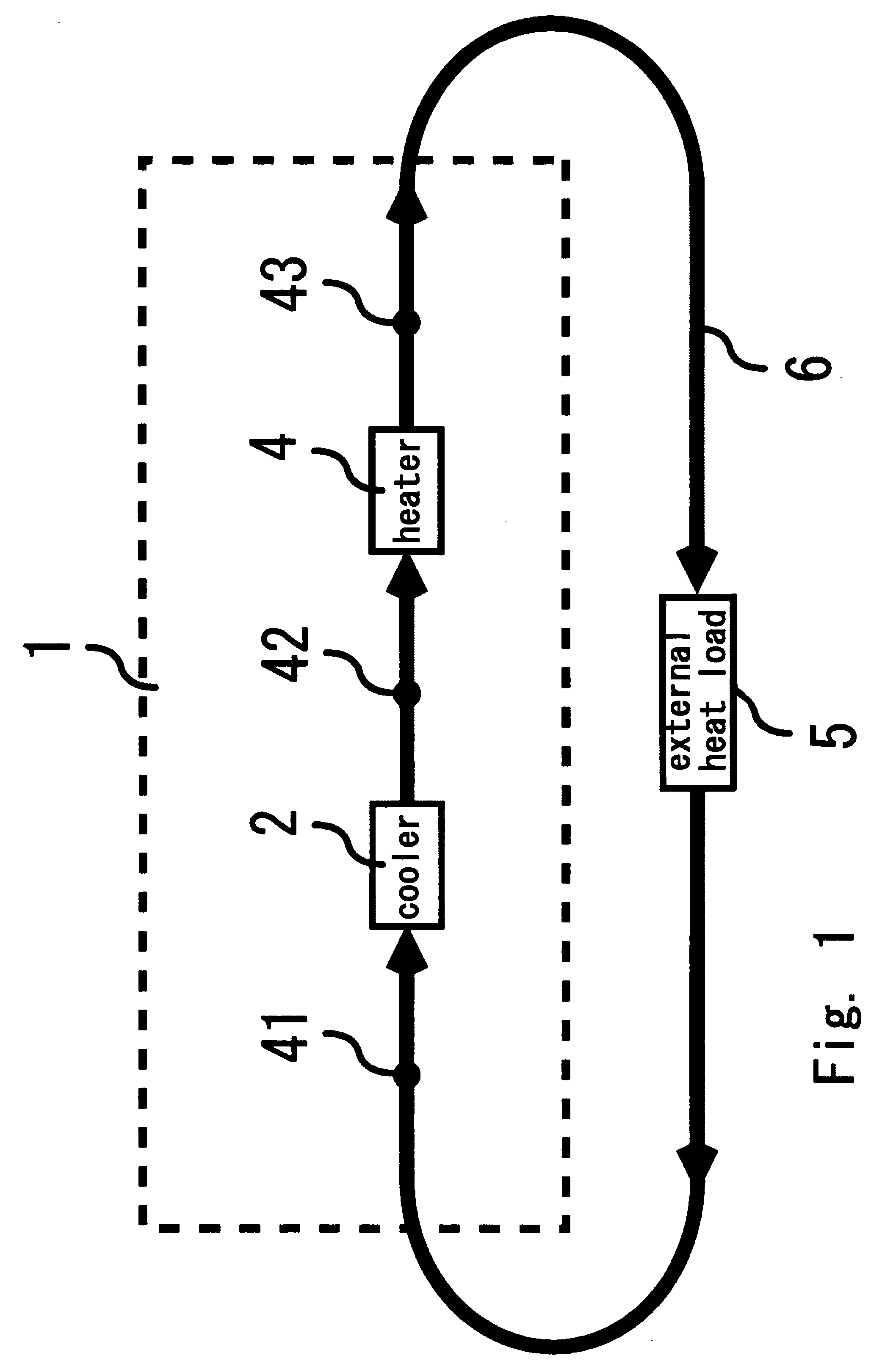
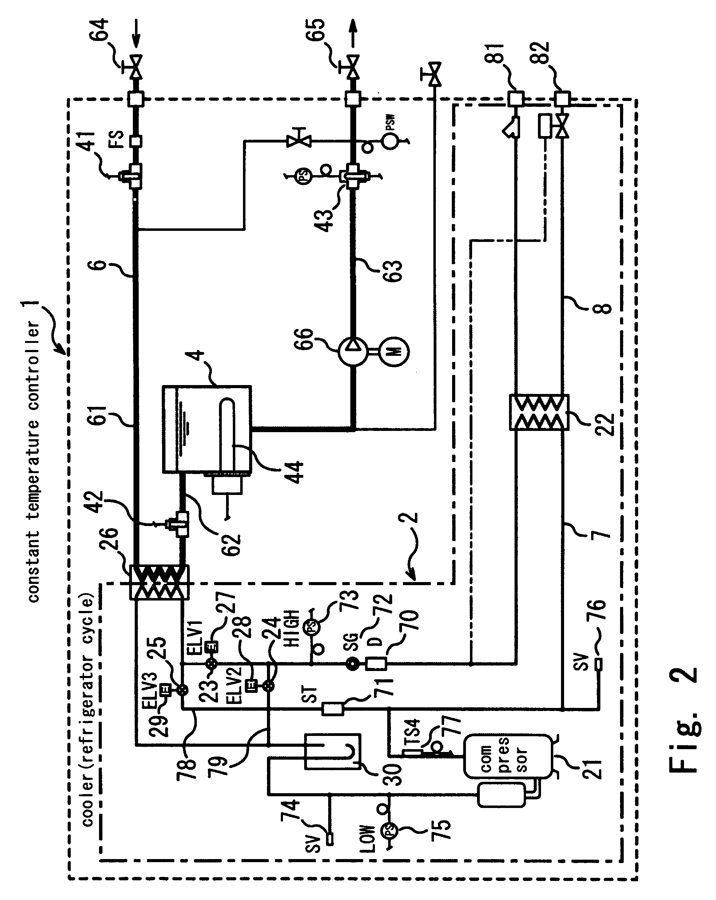
[0048]FIG. 1 is a block diagram schematically showing a configuration of a constant temperature controller, in which a portion enclosed by broken lines constitutes the constant temperature controller 1. The constant temperature controller 1 includes a cooler 2 and a heater 4. Numeral 5 designates an external heat load apparatus to be maintained at a constant temperature, such as an etching apparatus for semiconductor wafers, connected to the constant temperature controller via a pipeline 6 for a circulating fluid so as to constitute a closed loop.

[0049] In the pipeline 6, water is sealed in to serve as a heat medium. To the pipeline 6, temperature sensors for measuring the temperature of the heat medium are attached at some points. 41 designates a first temperature sensor that measures the circulating fluid temperature at the inlet port of the cooler, i.e. the temperature of the circulating fluid returning from the external heat load; 42 a second temperature sensor that measures th...


PUM


Abstract

A constant temperature controller inexpensive and easy to operate, yet capable of accurately controlling the temperature with significantly reduced heat energy consumption, is provided. An operation mode of a cooler is switched between an idling mode and a loaded mode, based on a difference in temperature between a first temperature sensor and a third temperature sensor. For switching the operation mode, cooling power of the cooler is adjusted by changing a frequency of an inverter driving a compressor. Under the loaded mode, the cooling power of the cooler is adjusted by an aperture of an electronic expansion valve such that a difference between a temperature of a second sensor and a target temperature of a heater becomes a constant value.

Description

FIELD OF THE INVENTION [0001] The present invention relates to a constant temperature controller for maintaining the temperature of an external heat load apparatus constant, and more particularly to a constant temperature controller that circulates a heat medium fluid of a constant temperature so as to maintain the temperature of the external heat load apparatus constant, employed for a chiller incorporated in a semiconductor manufacturing apparatus, or the like. DESCRIPTION OF THE RELATED ART [0002] A conventional constant temperature controller, generally called a chiller, is designed to circulate a heat medium fluid through a pipeline arranged in a loop through a cooler, a heater and an external heat load apparatus, so as to once supercool the liquid medium heated by the external heater with the cooler, and to heat the supercooled liquid medium with the heater thus to supply the external heat load apparatus with the liquid medium of a predetermined temperature specified by the ex...

Claims


Application Information

Patent Timeline
Patent Type & Authority Applications(United States)
IPC IPC(8): F25B29/00
CPCF25B49/02F25B2341/0653F25B2400/0403F25B2400/0409F25B2400/24Y02B30/741F25B2700/21172F25B2700/21173F25D17/02Y02B30/72F25B2600/021Y02B30/70F25B41/35H01L21/3065H01L21/02
Inventor SHIMIZU, KAZUSHIGE
Owner ATS
Why Eureka
Try Eureka