Semiconductor-type three-axis acceleration sensor
a three-axis acceleration and sensor technology, applied in the direction of speed/acceleration/shock measurement, measurement devices, instruments, etc., can solve the problems of reducing the absolute value of output, difficult to thin the acceleration sensor, and difficult to accurately produce a slight space between the auxiliary weight and the support frame in using a silicon substrate. , to achieve the effect of small output difference, high shock resistance and small siz
- Summary
- Abstract
- Description
- Claims
- Application Information
AI Technical Summary
Benefits of technology
Problems solved by technology
Method used
Image
Examples
experiment 1
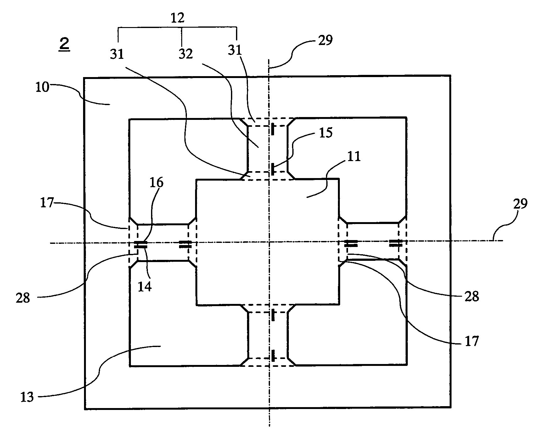
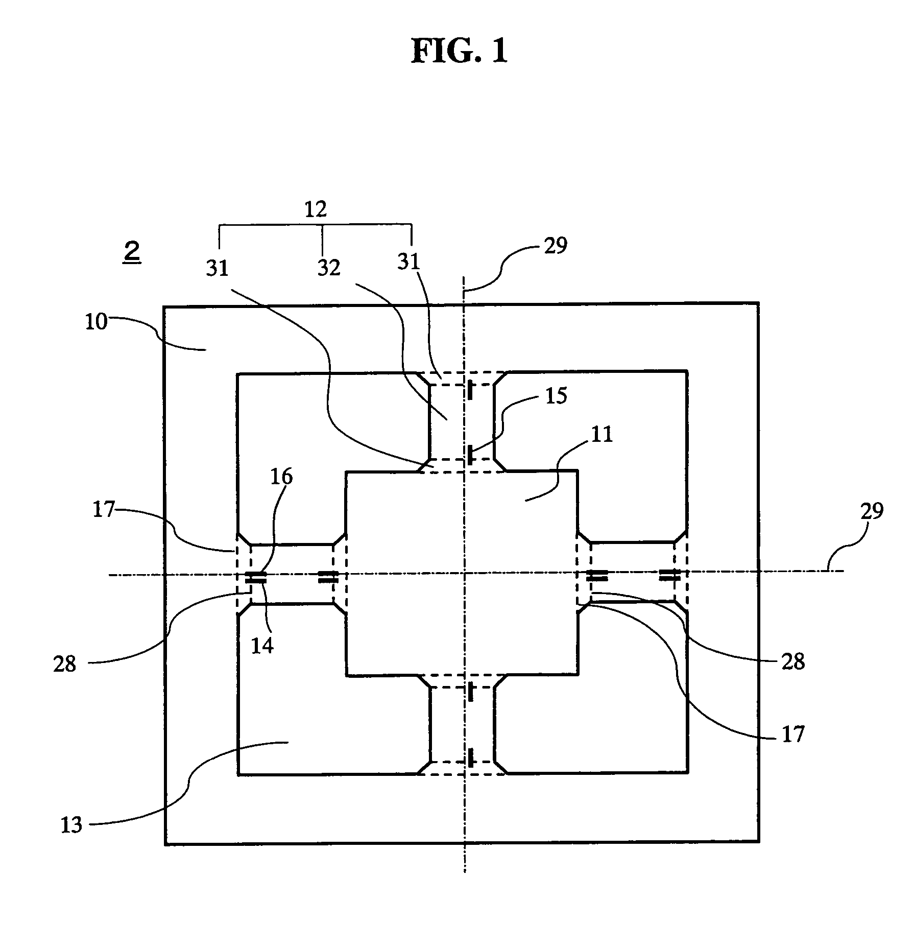
[0091]FIG. 5 is a graph showing a relationship of outputs to positions (L3) of maximum stress parts with a radius R of ridges of a flexible widening part as a parameter. FIG. 5 shows a case where the ridges of the flexible widening part 31 are ¼ circular arc. The flexible widening part, of which the ridges are a straight line or a noncircular arc, showed a similar tendency, so that the graph of the ¼ circular arc is shown here as a representative. In FIG. 5, radius R=0 μm means that the flexible winding part 31 does not exist, which shows a conventional sensor element only with a flexible parallel part 32 on a flexible arm. A maximum stress part in the conventional sensor element was at a connection end 17 of a flexible arm, at which L3=0 μm, and when a terminal of a piezo resistor 14, (15 or 16) was located at the connection end, an output of the piezo resistor was set to 100%. Positions (L3) indicating the maximum stress part were obtained while changing a radius R to 20 μm, 50 μm...
experiment 2
[0093]The following is a description of how to improve a shock resistance by providing a flexible widening part. FIG. 6 is a graph showing a relationship of shock resistances to lengths L1 of the flexible widening part, in which ridges of the flexible widening part are formed by a ¼ circular arc (R) with a radius R of 0 μm to 70 μm or a straight line with an angle of 45 degrees and in which distance (length L1 of the flexible widening part) between a connection end 17 of a flexible arm and a connection end 28 of a flexible parallel part is changed between 0 μm to 45 μm. Twenty acceleration sensors for each ridge were produced for shock resistance tests. A pendulum impact tester was used for the shock resistance test. An impacting time was set at 0.2 milliseconds. Accelerations of 1000 G to 5000 G were applied in steps of 100 G. Shock resistances may vary with direction, so that eighteen impacts, that is, six directions (a positive and a negative directions of X-axis, Y-axis and Z-ax...
experiment 3
[0095]FIG. 7A is a graph showing a relationship of shock resistances (KG) and outputs (%) to W2 / W1, the ratio of the width W2 of the flexible parallel part 32 to the width W1 of the flexible widening part at the connection end 17 of the flexible arm. The width W2 of the flexible parallel part 32 in the flexible arm 12 was kept constant at 75 μm. As shown in the legends of FIG. 7B, the ridges of the flexible widening part were changed to ¼ circular arc with a radius R (indicated by ▪ and □), a straight line (indicated by ● and ∘), a mountain shape being steep in the vicinity of the connection end of the flexible arm (indicated by ▴ and Δ), and a bell shape changing sharply in shape in the vicinity of the connection end of a flexible parallel part (indicated by ♦ and ⋄). Twenty samples of the acceleration sensors with these ridges for each of the shapes were produced and evaluated by the same method as in the experiment 2 in the shock resistance test. Acceleration of 3 G was applied t...
PUM
 Abstract
Description
Claims
Application Information
 - R&D
- Intellectual Property
- Life Sciences
- Materials
- Tech Scout
- Unparalleled Data Quality
- Higher Quality Content
- 60% Fewer Hallucinations
Browse by: Latest US Patents, China's latest patents, Technical Efficacy Thesaurus, Application Domain, Technology Topic, Popular Technical Reports.
© 2025 PatSnap. All rights reserved.Legal|Privacy policy|Modern Slavery Act Transparency Statement|Sitemap|About US| Contact US: help@patsnap.com


