Refrigeration system

a technology of refrigeration system and refrigeration system, which is applied in the direction of valve details, lighting and heating apparatus, compression machines with non-reversible cycles, etc., and can solve problems such as inferior importan

Inactive Publication Date: 2014-04-08
DANFOSS AS
View PDF29 Cites 19 Cited by
  • Summary
  • Abstract
  • Description
  • Claims
  • Application Information

AI Technical Summary

Benefits of technology

[0008]When the distributor comprises a controllable valve for each evaporator, it can control the supply of the evaporators individually, that is, it is then possible to supply each evaporator with the amount of refrigerant it requires. It no longer has to be ensured that all evaporators have the same flow resistance. It is also von inferior importance, if the evaporators have to supply different cooling outputs. An evaporator, from which a larger cooling output is required, receives correspondingly more refrigerant that an evaporator, which has to supply a smaller cooling output. In a simple manner, the control of the valves occurs by means of a magnet arrangement comprising at least one magnet. A magnet exerts magnet forces on valves or parts of valves, if the magnet is in the vicinity of the valve and is active. If, on the other hand, the magnet is far away from the valve or is passive, for example a disconnected electric magnet, it exerts no forces on this valve or parts of it. Thus, by means of a control of the position and / or the function of the magnet, it can be ensured that a certain valve is opened, while other valves remain closed.
[0011]Preferably, the magnet acts through a closed wall of the housing. This has the advantage that an activation of the valves does not require an opening for the entry of a tappet or the like. If such an opening is not present, also the problem of a possible leakage does not occur. The only condition for such an embodiment is that the wall does not hinder the effect of the magnet. A plastic material, for example, permits a practically undisturbed passage of a magnetic field. The same also applies for many non-magnetic metals.
[0012]Preferably, the magnet is guided in a circumferential groove. Thus, the groove defines a circular path, in which the magnet can move. Thus, it is sufficient to fix the magnet to the rotor in the circumferential direction. The circumferential groove ensures that in the radial direction the magnet will always maintain the correct positioning in relation to the valves.
[0018]Preferably, the auxiliary valve element interacts with a closing spring. The closing spring does not have to provide large forces. It must merely be able to bring the auxiliary valve element to rest on an auxiliary valve seat. When the distributor is mounted so that the auxiliary valve element will come to rest on the auxiliary valve seat under the effect of the gravity, a closing spring may be avoidable. However, with a closing spring the advantage exists that choice of the mounting position is substantially free.
[0020]It is also preferred that each valve is provided with its own controllable magnet. Also such a magnet can be an electric magnet. This embodiment has the advantage that the valves can be controlled independently of one another, that is, also in a more or less random order. Also here all valves can be opened simultaneously when starting the refrigeration system.

Problems solved by technology

It is also von inferior importance, if the evaporators have to supply different cooling outputs.

Method used


Image

  • Refrigeration system
  • Refrigeration system
  • Refrigeration system

Examples


Embodiment Construction

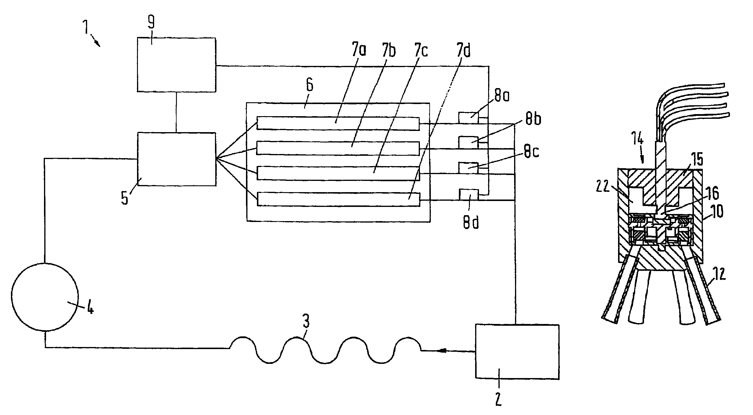
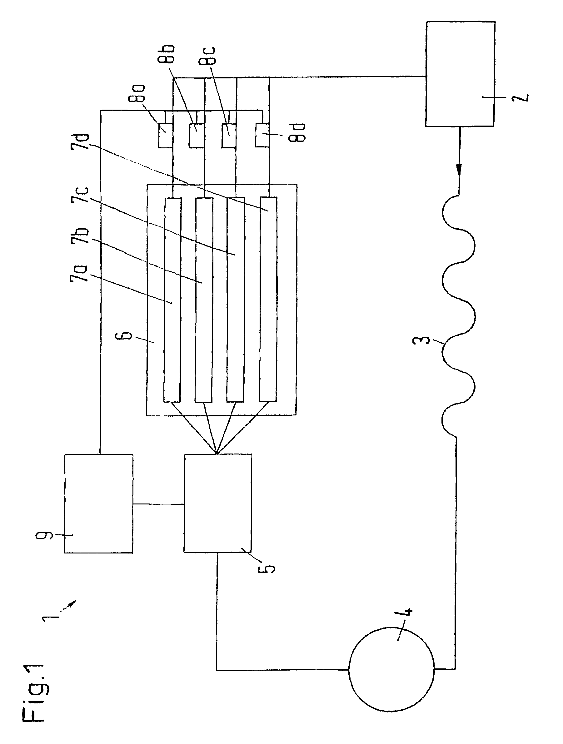
[0028]FIG. 1 shows a schematic view of a refrigeration system 1, in which a compressor 2, a condenser 3, a collector 4, a distributor 5 and an evaporator arrangement 6 with several parallel-connected evaporators 7a-7d are joined to a circuit. The evaporator arrangement 6 can also have one single evaporator comprising several evaporator paths, which can be controlled individually or in groups.

[0029]In a manner known per se, liquid refrigerant evaporates in the evaporators 7a-7d, is compressed by the compressor 2, liquefied in the condenser 3 and collected in the collector 4. The distributor 5 is provided to distribute the liquid refrigerant to the individual evaporators 7a-7d.

[0030]At the outlet of each evaporator 7a-7d a temperature sensor 8a-8d is arranged. The temperature sensors 8a-8d determine the temperature of the refrigerant leaving the evaporators 7a-7d. This temperature information is passed on to a control unit 9 that controls the distributors in dependence of the tempera...


PUM


Abstract

A refrigeration system includes a refrigerant circuit with a plurality of evaporator paths and a distributor for distributing refrigerant. The distributor includes a housing and a controllable valve for each evaporator path. The refrigeration system is operated by using a distributor including a magnet arrangement for controlling the valves.

Description

CROSS REFERENCE TO RELATED APPLICATIONS[0001]This application is entitled to the benefit of and incorporates by reference essential subject matter disclosed in International Patent Application No. PCT / DK2008 / 000223 filed on Jun. 17, 2008 and German Patent Application No. 10 2007 028 565.7 filed Jun. 19, 2007.FIELD OF THE INVENTION[0002]The invention concerns a refrigeration system with a refrigerant circuit comprising several evaporation paths and a distributor causing a distribution of refrigerant, the distributor comprising a housing and a controllable valve for each evaporation path.BACKGROUND OF THE INVENTION[0003]Such a refrigeration system is known from DE 195 47 744 A1. The known refrigeration system comprises one single compressor and one single condenser, but two evaporators, which are made separately from one another. The refrigerant flow delivered by the compressor is divided into two partial flows after the condenser and before the expansion valves by means of a 3 / 2-way ...

Claims


Application Information

Patent Timeline
Patent Type & Authority Patents(United States)
IPC IPC(8): F25B39/02
CPCF25B2600/2511F25B2500/01F25B39/028F25B41/48
Inventor BIRKELUND, MICHAELPETERSEN, HANS KURTPRYTZ, SUNE
Owner DANFOSS AS
Why Eureka
Try Eureka