Refrigeration system
- Summary
- Abstract
- Description
- Claims
- Application Information
AI Technical Summary
Benefits of technology
Problems solved by technology
Method used
Image
Examples
Embodiment Construction
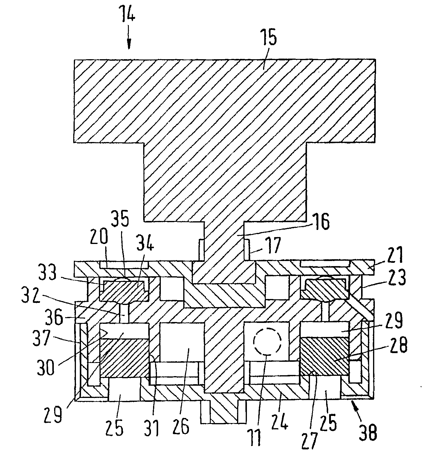
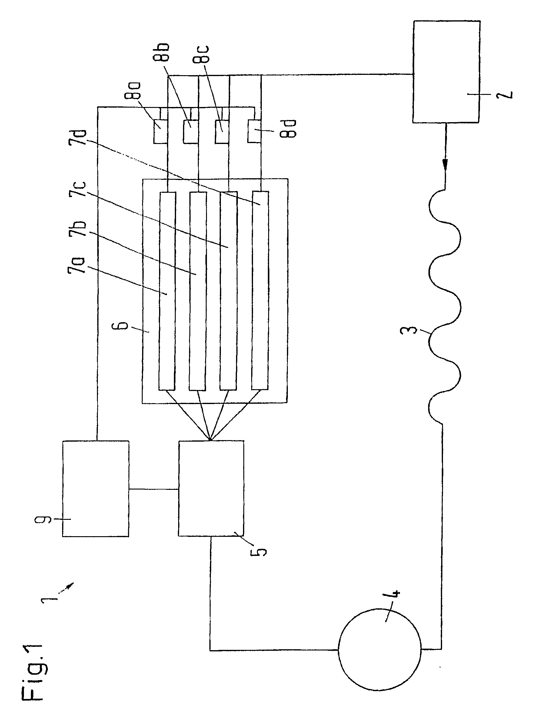
[0028]FIG. 1 shows a schematic view of a refrigeration system 1, in which a compressor 2, a condenser 3, a collector 4, a distributor 5 and an evaporator arrangement 6 with several parallel-connected evaporators 7a-7d are joined to a circuit. The evaporator arrangement 6 can also have one single evaporator comprising several evaporator paths, which can be controlled individually or in groups.
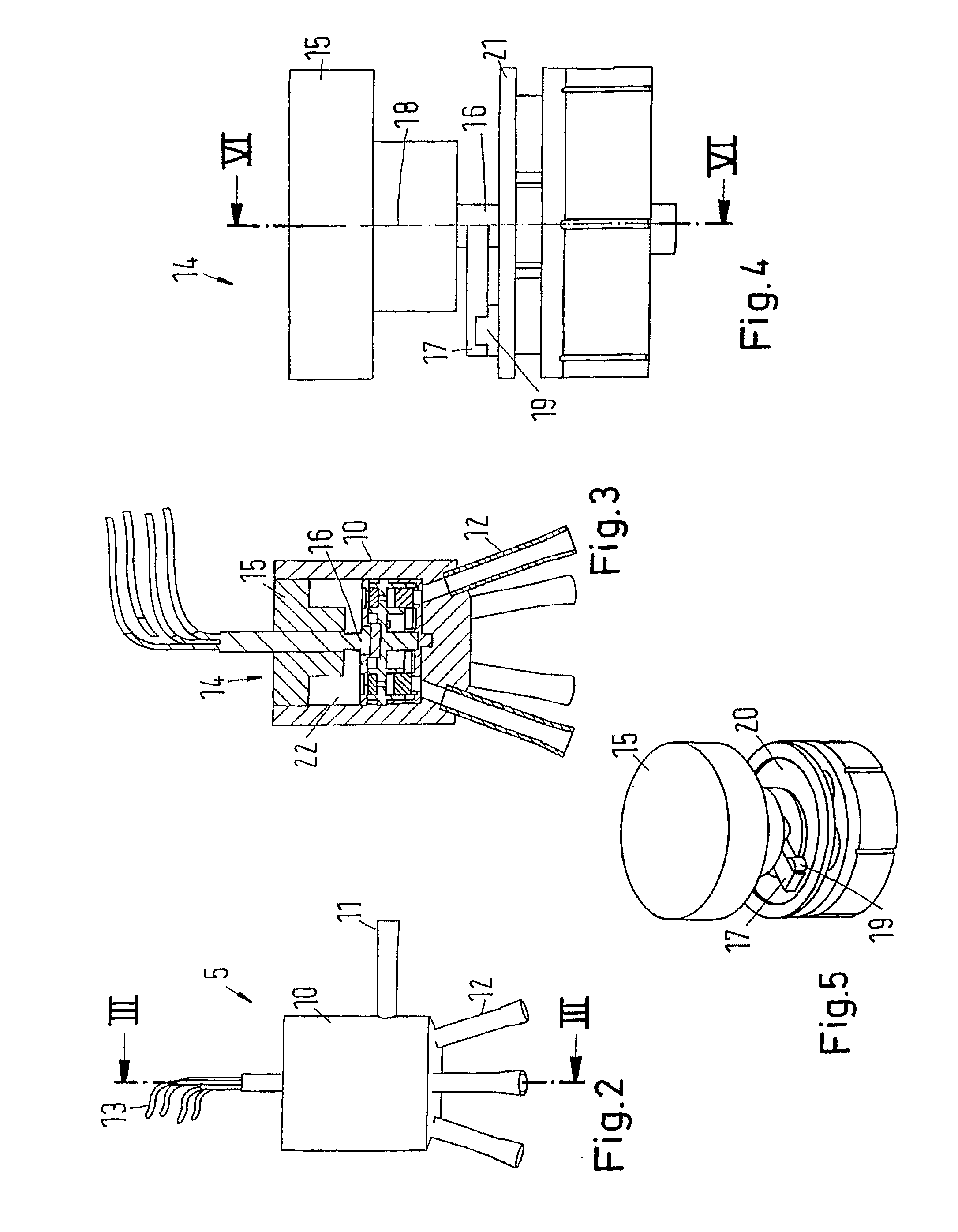
[0029]In a manner known per se, liquid refrigerant evaporates in the evaporators 7a-7d, is compressed by the compressor 2, liquefied in the condenser 3 and collected in the collector 4. The distributor 5 is provided to distribute the liquid refrigerant to the individual evaporators 7a-7d.
[0030]At the outlet of each evaporator 7a-7d a temperature sensor 8a-8d is arranged. The temperature sensors 8a-8d determine the temperature of the refrigerant leaving the evaporators 7a-7d. This temperature information is passed on to a control unit 9 that controls the distributors in dependence of the tempera...
PUM
 Abstract
Description
Claims
Application Information
 - R&D
- Intellectual Property
- Life Sciences
- Materials
- Tech Scout
- Unparalleled Data Quality
- Higher Quality Content
- 60% Fewer Hallucinations
Browse by: Latest US Patents, China's latest patents, Technical Efficacy Thesaurus, Application Domain, Technology Topic, Popular Technical Reports.
© 2025 PatSnap. All rights reserved.Legal|Privacy policy|Modern Slavery Act Transparency Statement|Sitemap|About US| Contact US: help@patsnap.com


