Squeeze film damper with highly variable support stiffness

a film damper and support technology, applied in the field of films, can solve the problems of difficult to predict the true bearing stiffness and the film damper will not allow air entrainment, and achieve the effects of reducing the overall length and distance between bearings, reducing weight, and controlling damping and stiffness independently

Inactive Publication Date: 2010-09-21
FLORIDA TURBINE TECH
View PDF30 Cites 40 Cited by
  • Summary
  • Abstract
  • Description
  • Claims
  • Application Information

AI Technical Summary

Benefits of technology

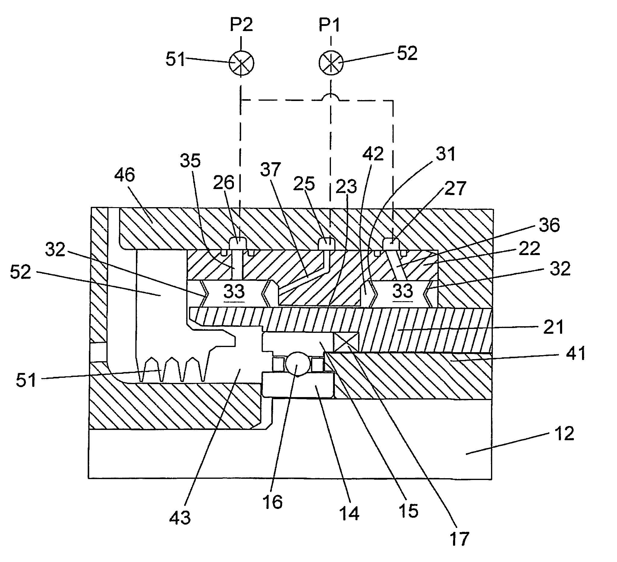
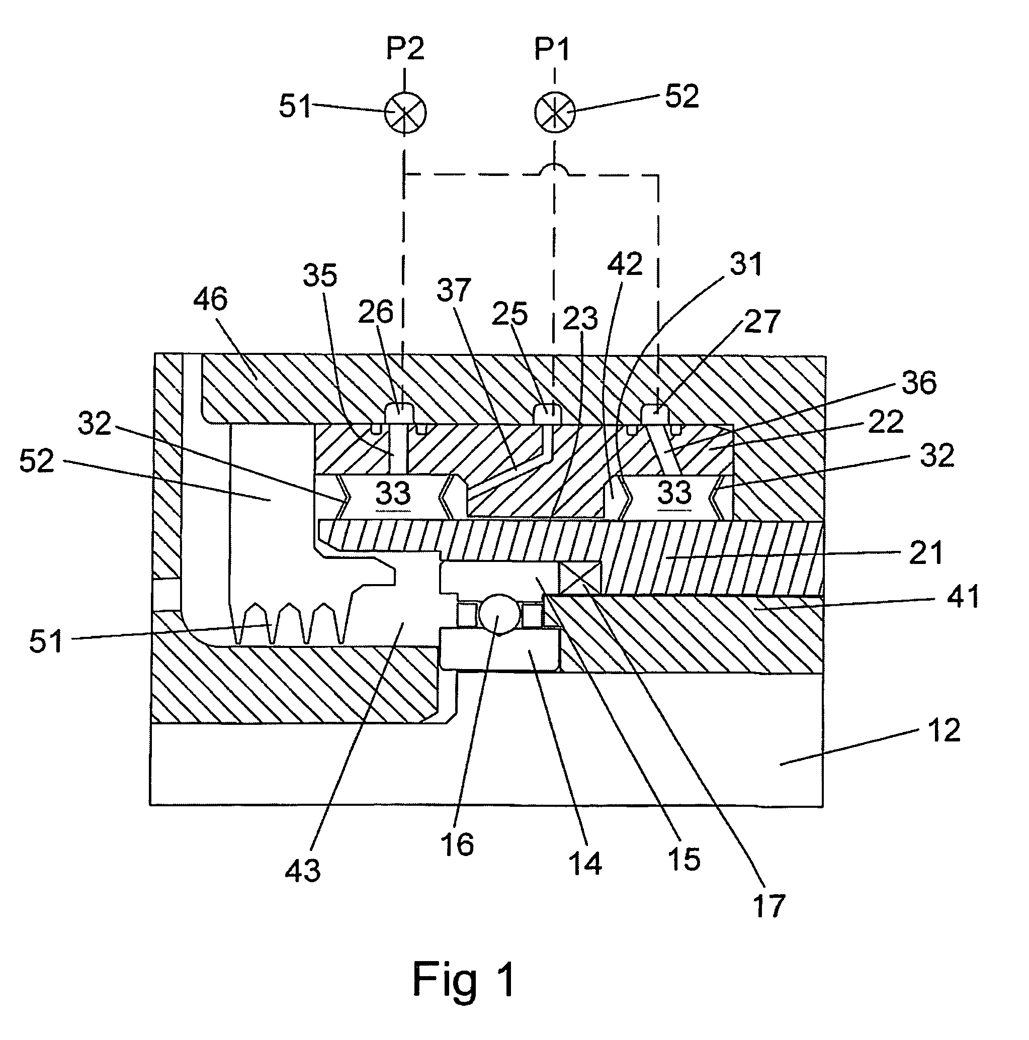
[0016]The present invention is a squeeze film damper located directly over the rolling element bearing, in which the squeeze film damper is formed of two annuli of fluid contained by a metal bellows located on either side of the squeeze film damper. The bellows forms an inner chamber that contains the damping fluid for the squeeze film damper, and an outer chamber in which the fluid pressure is regulated to control the pressure in the squeeze film damper chamber. A first and a second pressure source is used to regulate the pressures in both of these chambers to control the damping and stiffness independently. The pressurized metal bellows flexes inwardly to provide for a variable spring force to center the bearing independent of the operating speed, provides for the separation of the damper fluid and the secondary fluids with zero leakage, requires less axial length leading to significant weight reduction and reducing the overall length and distance between bearings in order that the bending mode natural frequency is higher, and reduces the overall size and weight of the turbomachine. The squeeze film damper will not allow air entrainment because it will have fluid reservoirs on either side of the squeeze film damper. The squeeze film damper can be pressurized with the working fluid or an alternative fluid separated from the working fluid. The flexible bellow having the inward flexibility provides a higher variability in stiffness than the previous invention by this applicant while also providing for zero leakage.
[0017]By controlling the pressure in the bellows, the spring rate of the support system can be changed rapidly and accurately. This variable spring rate can be leveraged to manipulate rigid body critical speeds. The capability to move critical speeds is very important for several reasons. First, by moving the critical speeds around, the modes can be avoided all together during startup. For instance, during startup, the bellows are pressurized to the highest pressure possible. By having the pressure high in the bellows, the spring rate is at its maximum, and therefore the rigid body modes are also at their highest speed. When the first rigid body is approached, the pressure in the bellows is suddenly reduced and therefore the spring rate is drastically reduced. By both accelerating and rapidly reducing the spring rate, the passage through the critical speed is traversed extremely quickly. By limiting the time at the critical speed, any rotor response from the critical speed will be minimal. Another benefit to moving around the critical speeds is the ability to operate anywhere on the rpm scale to obtain extremely deep throttling capability. By either increasing or decreasing the stiffness at a given rpm, a critical speed can be moved so that operation at that speed is possible. This allows any rigid body vibration mode to be relocated so that peak performance can be obtained and startup profiles are independent of rigid body vibration modes.
[0018]The proposed configuration allows the pressurized bellows to provide a positive direct stiffness in series with the bearing. By directing the load through the bearing and then through the pressurized bellows and squeeze film damper in series instead of in parallel like most turbo-pumps, some of the load-carrying requirement is removed from the bearing, enhancing life. Since the pressurized bellows stiffness will be highly controllable and typically lower than the bearing stiffness, the fluid film will respond to dynamic loads thereby decreasing the dynamic load on the bearing. The squeeze film damper will dissipate and dampen the vibrations that would normally be transmitted directly to the housing. The reduction of dynamic loads to the housing will increase the life of any HCF limited turbopump component. Another benefit of the positive load capacity of the pressurized bellows is that the bearing will no longer have to run with a dead band clearance. Traditionally it is very difficult to predict the true bearing stiffness when a dead-band clearance is used. The elimination of this clearance linearizes the performance and characteristics of the rolling element bearing and makes its behavior easier to predict.
[0019]The new configuration allows the stiffness to be varied significantly more than the previous configuration. The stiffness can vary by a minimum of 300% or more, allowing the rigid body modes to be moved around to any desired speed. The new configuration also lends itself to more applications.

Problems solved by technology

The squeeze film damper will not allow air entrainment because it will have fluid reservoirs on either side of the squeeze film damper.
Traditionally it is very difficult to predict the true bearing stiffness when a dead-band clearance is used.

Method used


Image

  • Squeeze film damper with highly variable support stiffness
  • Squeeze film damper with highly variable support stiffness

Examples


Embodiment Construction

[0022]The squeeze film damper with variable stiffness support of the present invention is shown in FIG. 1. A rotor shaft 12 for a turbomachine is supported by a roller element bearing having an inner race 14, and outer race 15, and a roller element such as a ball 16 between the races. A labyrinth seal 51 extends from a support 52 secured to a stationary housing or casing 26 of the turbomachine to form a seal on the side of the bearing. A squeeze film damper is inner member 21 and an outer member 22 in which a squeeze film damper chamber 23 is formed between adjacent surfaces of the two members. The outer member 22 is supported by the casing 26, and the inner member 21 supports the outer race 15 of the bearing.

[0023]An annular bellows assembly is positioned between surfaces on the outer member 22 and the inner member 21. The bellows assembly includes an inner bellows 31 and an outer bellows 32 that define a bellows chamber 33. The top ends of the inner and the outer bellows 31 and 32...


PUM


Abstract

A squeeze film damper assembly having a variable stiffness and damping control. The squeeze film damper includes a damper chamber formed by two flexible bellows chambers of the sides. A first pressure source is applied to the damper chamber to regulate the damping. A second pressure source is applied to the flexible bellows chambers to vary the stiffness of the damper. The flexible bellows chambers are secured between an outer member and an inner member of the damper assembly and form the sealed damper chamber. A pressure ratio between the bellows chambers and the damper chamber can vary to control the stiffness of the squeeze film damper.

Description

CROSS-REFERENCE TO RELATED APPLICATIONS[0001]This application is related to US Regular utility patent application Ser. No. 11 / 524,018 filed on Sep. 20, 2006 and entitled SQUEEZE FILM DAMPER WITH VARIABLE SUPPORT STIFFNESS, now U.S. Pat. No. 7,517,152 B1 issued on Apr. 14, 2009.BACKGROUND OF THE INVENTION[0002]1. Field of the Invention[0003]The present invention relates generally to bearings, and more specifically to a squeeze film damper for a bearing in which the damper has variable damping.[0004]2. Description of the Related Art Including Information Disclosed Under 37 CFR 1.97 and 1.98[0005]A turbomachine, such as a turbopump, utilizes damper seals and rigidly mounted rolling element bearings to dampen and rotatably support the shaft. Prior Art turbo pumps use an interstage bearing and damper seals to provide support and damping to the rotor. Damper seals provide positive stiffness but require leakage flow to operate. Squeeze film dampers (SFD) are inherently stable and do not pr...

Claims


Application Information

Patent Timeline
Patent Type & Authority Patents(United States)
IPC IPC(8): F16C27/00
CPCF04D29/126F16C27/04F16C27/045F16C35/077F16F15/0237F16F15/027F04D29/668F16C19/06F16C2360/00
Inventor WALSH, WILLIAM S.
Owner FLORIDA TURBINE TECH
Why Eureka
Try Eureka