Laser system and method for generation of a pulse sequence with controllable parameters and computer program product

a technology of computer program product and laser system, which is applied in the direction of laser arrangement, laser details, optical resonator shape and construction, etc., can solve the problems of high temporal inertia, high cost and inefficiency of methods, etc., and achieve the effect of increasing the overall amplification increasing the effective amplification bandwidth of the laser system, and increasing the overall amplification bandwidth

Active Publication Date: 2006-10-03
TECHNOLAS PERFECT VISION +1
View PDF37 Cites 40 Cited by
  • Summary
  • Abstract
  • Description
  • Claims
  • Application Information

AI Technical Summary

Benefits of technology

[0015]Any light pulse can be defined by its physical parameters such as wavelength, bandwidth, pulse duration (or temporal width), pulse form, pulse energy, location in time (or pulse timing) and further parameters derived from these. For example, a pulse sequence denoted {Pi}={E0; T0; τ0; Pi(ΔEi; ΔTi; Δτi)} may be defined recursively by the energy E0, the point in time T0, and the temporal width (duration) τ0 of the initial laser pulse P0, as well as the energy differences ΔEk=Ek−Ek-1, the distance in time ΔTk=Tk−Tk-1 of the k-th pulse to its predecessor (k-1-th pulse), and the difference in temporal width Δτk=τk−τk-1. Formally, ΔE0=ΔT0=Δτ0=0 is defined. According to the invention, the specified (or the desired) pulse sequence {Pi} can be predetermined or can be predeterminable (or dynamically controlled) during the pulse emission. Thus, depending on application, specific, application-dependent pulse and / or pulse sequence with specified (predetermined or predeterminable) properties or a combination of these can be generated and preferably adjusted dynamically, allowing for example a synchronization of pulse generation with asynchronous external processes. Moreover, since pulse sequences with desired parameters are directly generated rather than obtained by simply selecting a part of the already generated pulse sequence, the system particularly allows for an efficient use of the available energy. Another advantage is that certain properties of the pulse sequence may be controlled independently from each other, so that pulses having specified (predetermined or predeterminable) parameters may be generated.
[0070]Increasing the security of the laser surgery, since the energy level can be predetermined and controlled preferably already at the time of generation of the individual pulse;

Problems solved by technology

This method is expensive and not efficient, since a large part of the generated laser energy is not used.
However, with the available technical means this is only possible with relatively high temporal inertia.

Method used


Image

  • Laser system and method for generation of a pulse sequence with controllable parameters and computer program product
  • Laser system and method for generation of a pulse sequence with controllable parameters and computer program product
  • Laser system and method for generation of a pulse sequence with controllable parameters and computer program product

Examples


Embodiment Construction

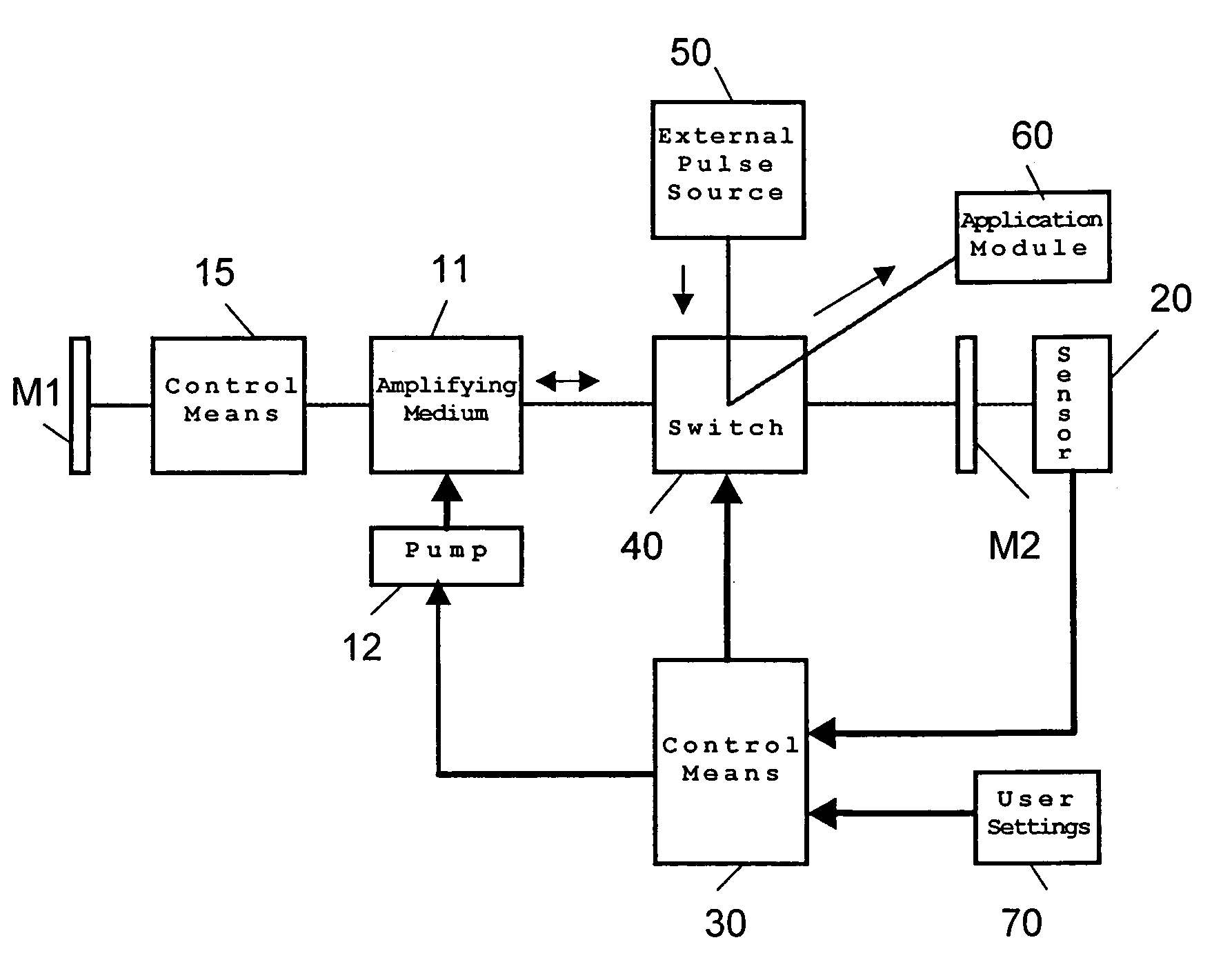
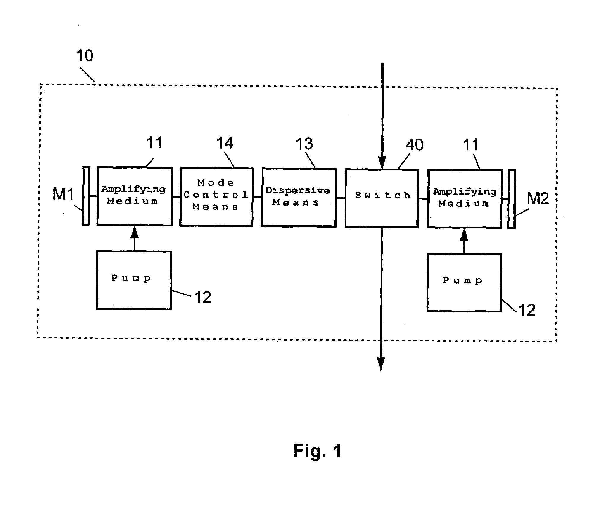
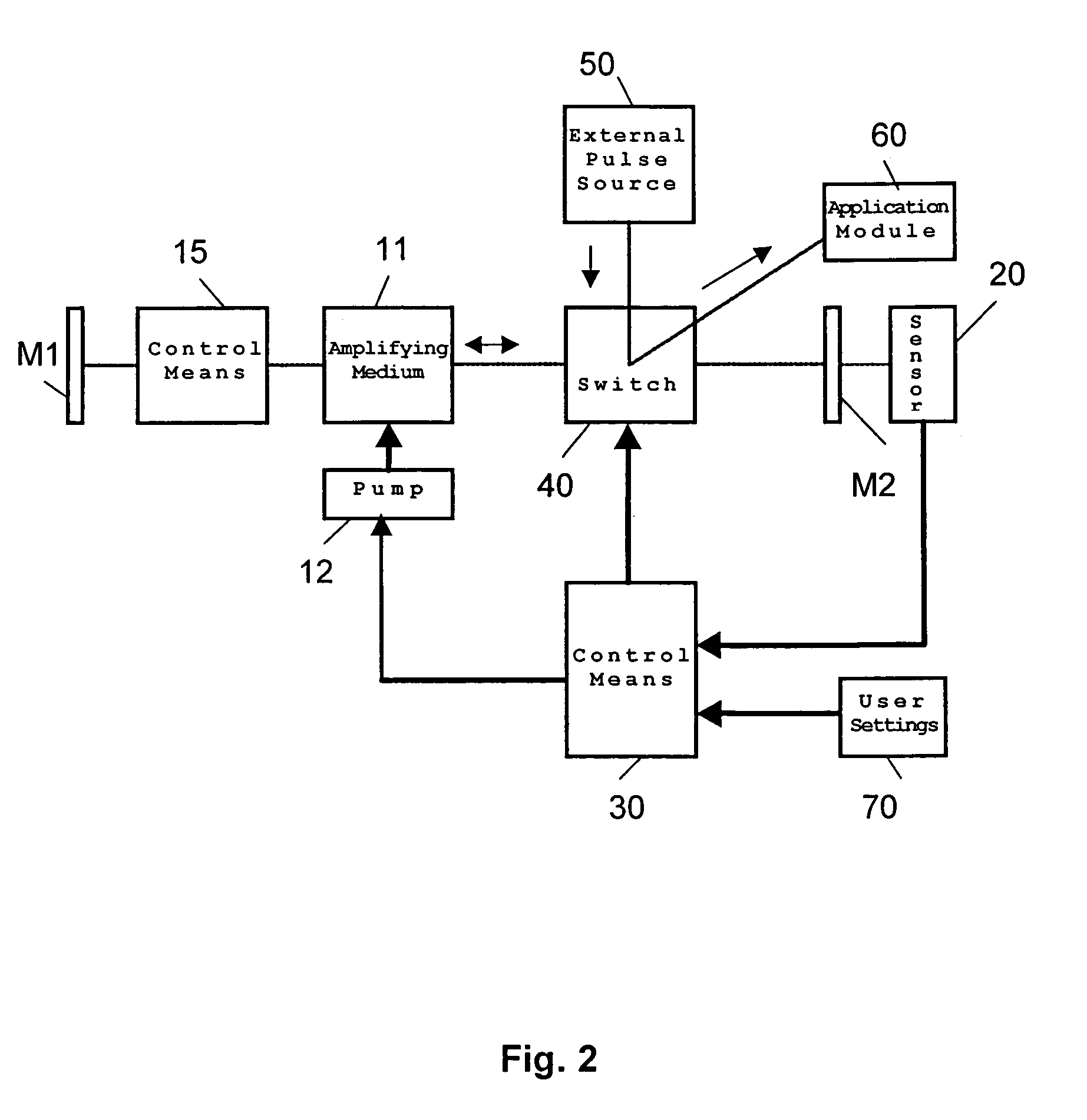
[0091]FIG. 1 schematically represents an amplifying cavity 10 according to a preferred embodiment of the present invention.

[0092]The end surfaces M1 and M2 define an amplifying cavity (also called laser cavity) 10. The end surfaces M1 and M2 are preferably mirrors, which can be plane, concave, or of other appropriate shape. It is further desirable that the losses on the end-surfaces and throughout the laser cavity are kept to minimum—i.e. that low loss optic is employed.

[0093]The amplifying cavity 10 comprises at least one amplifying medium 11 (also denoted as gain medium or laser rod). The amplifying medium 11 is pumped by the pump 12, which may be a flash lamp, laser diode or other suitable pumping means, preferably through pumping optics.

[0094]Further within the amplifying cavity 10 there is positioned a switching means (or in short a switch) 40.

[0095]Preferably, the laser cavity 10 may comprise also at least one dispersive means 13 for manipulating the dispersion characteristics...


PUM


Abstract

A laser system for generating at least one pulse and / or pulse sequence(s) of pulses having at least one specified property, such as pulse energy, duration, peak intensity, pulse form and / or timing includes an amplifying cavity. The amplification process is monitored in the amplifying cavity to obtain data about at least one property of the pulse sequence and / or the single pulse(s). The system also compares the obtained data with reference data and it controls at least one switching means for inputting, outputting and / or retaining the pulse(s) in the amplifying cavity such that at least one property of the pulse sequences and / or the pulses at an output of the laser system has substantially a specified value.

Description

[0001]The foreign priority benefit of the prior filing date of Feb. 14, 2003 for foreign application number 03003459.9 filed in Europe is claimed for the present application.FIELD OF THE INVENTION[0002]The invention refers to a laser system, a controller and a method for generation of at least one pulse and / or a pulse sequence(s) with controllable parameters such as pulse energy, pulse duration, pulse timing, pulse peak energy, pulse form, pulse, repetition rate, and timing and / or parameters derived from them, as well as to a computer program. In particular the invention refers to a generation of controllable pulse sequences of ultrashort (femto- and picosecond) pulses.[0003]The wide range of application areas contains, but is not limited to, laser material processing, medical applications of lasers such as e.g. laser microkeratome LMK, refractive corneal surgery, fs-LASIK, laser neurosurgery, optical measuring technology and / or data processing.BACKGROUND OF THE INVENTION[0004]Optic...

Claims


Application Information

Patent Timeline
IPC IPC(8): H01S3/10H01S3/117H01S3/08H01S3/131H01S3/136H01S3/139H01S3/23
CPCH01S3/235H01S3/0057H01S3/0606H01S3/08004H01S3/08059H01S3/09408H01S3/09415H01S3/10046H01S3/10069H01S3/10092H01S3/1022H01S3/1312H01S2301/04
Inventor SAUTER, THOMASZICKLER, LEANDER
Owner TECHNOLAS PERFECT VISION
Why Eureka
Try Eureka