System and Method for Selecting and Applying Appropriate Print Quality Defect Correction Technique to Compensate for Specified Print Quality Defect

a print quality defect and correction technique technology, applied in the field of imaging systems, can solve the problems of skew error, skew error, primarily manifest stitching error, etc., and achieve the effects of improving selection and application, eliminating adverse side effects, and improving capability

Inactive Publication Date: 2010-07-01
LEXMARK INT INC
View PDF4 Cites 116 Cited by
  • Summary
  • Abstract
  • Description
  • Claims
  • Application Information

AI Technical Summary

Benefits of technology

[0012]The present invention meets this need by providing an innovation that enhances capability to appropriately correct print quality defects, namely print skew, parallelism and white space errors, by improvement of selection and application of an appropriate print quality defect correction technique to compe...

Problems solved by technology

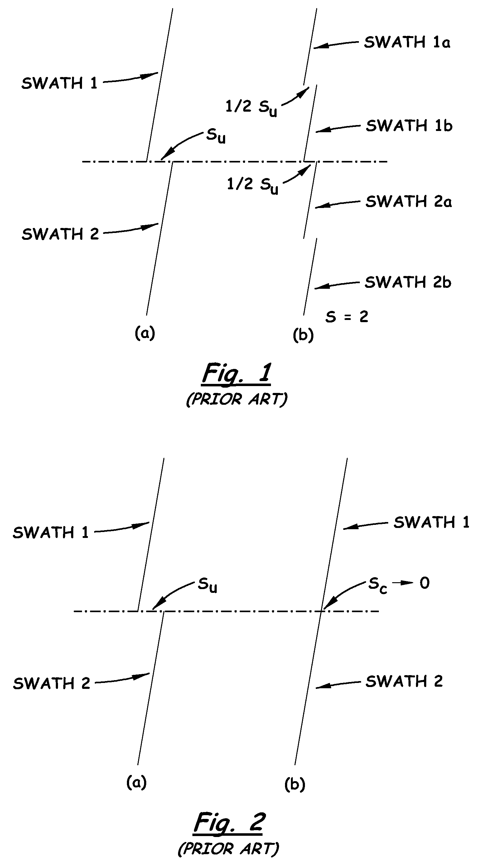
Stitching error primarily manifests itself in the printed output of inkjet printheads as horizontal offset between adjacent swaths.
This is a print quality defect known as skew error which refers to offset from true vertical.
Skew error occurs when the printhead is not oriented perpendicular to the direction of printhead carrier travel.
The effect of skew error is that features in a print swath are misaligned from true vertical and that features in a subsequent print swath do not line up with the features printed on a prior print swath.
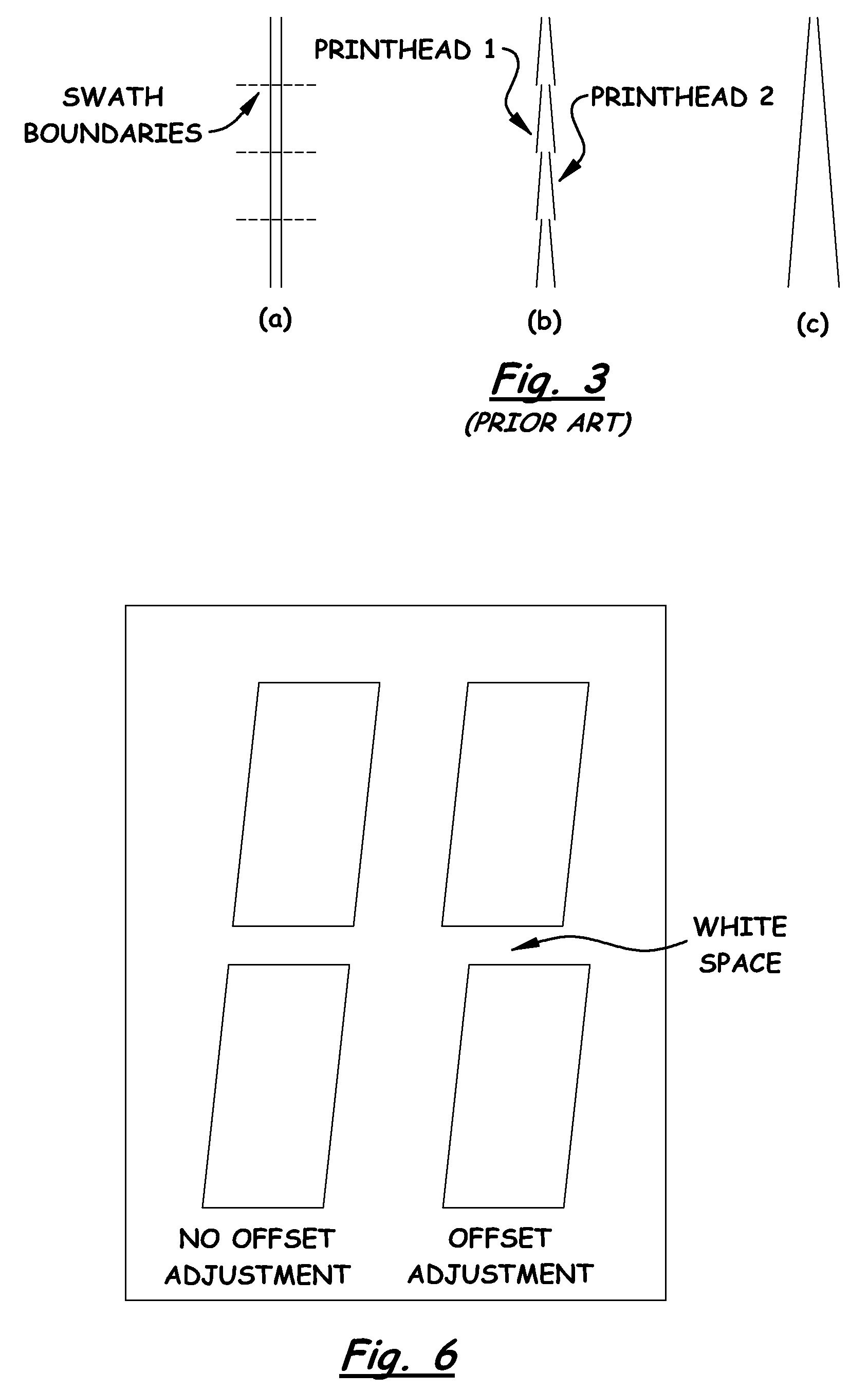
Stitching error is most noticeable in patterns of long vertical lines printed with a single color.
However, in actual practice, it becom...

Method used


Image

  • System and Method for Selecting and Applying Appropriate Print Quality Defect Correction Technique to Compensate for Specified Print Quality Defect
  • System and Method for Selecting and Applying Appropriate Print Quality Defect Correction Technique to Compensate for Specified Print Quality Defect
  • System and Method for Selecting and Applying Appropriate Print Quality Defect Correction Technique to Compensate for Specified Print Quality Defect

Examples


Embodiment Construction

[0025]The present invention now will be described more fully hereinafter with reference to the accompanying drawings, in which some, but not all embodiments of the invention are shown. Indeed, the invention may be embodied in many different forms and should not be construed as limited to the embodiments set forth herein; rather, these embodiments are provided so that this disclosure will satisfy applicable legal requirements. Like numerals refer to like elements throughout the views.

[0026]Referring now to FIG. 4, there is illustrated an exemplary embodiment of a prior art imaging system, generally designated 10, for employing improvements provided by the system and method of the present invention. The imaging system 10 includes a host computer 12 and an imaging apparatus 14, which, for example, may be in the form of a conventional inkjet printer. The host computer 12 may be separate from or a part of the imaging apparatus 14. The host computer 12 may be communicatively coupled to im...


PUM


Abstract

A system for selecting and applying an appropriate print quality defect correction technique to compensate for specified print quality defects includes a printhead deployed to perform an operation that forms an image on a print medium sheet composed of multiple adjacently-positioned swaths of print, a sensor mechanism deployed to perform an operation that scans the image, detects the presence of specified print quality defects in the multiple adjacently-positioned swaths of print, and generates an output corresponding to the detected defect, and a control mechanism communicating with and controlling operations of the printhead and sensor mechanism and storing an algorithm that responds to the sensor mechanism output by analyzing and comparing the output with a stored threshold value and when the output exceeds the stored threshold value selecting and applying an appropriate print quality defect correction technique to the printhead that compensates for the detected print quality defect in the multiple adjacently-positioned swaths of print in subsequent images that are formed by the printhead.

Description

CROSS REFERENCES TO RELATED APPLICATIONS[0001]None.BACKGROUND[0002]1. Field of the Invention[0003]The present invention relates generally to imaging systems, such as inkjet printers, and, more particularly, to a system and method for selecting and applying an appropriate print quality defect correction technique to compensate for a specified print quality defect.[0004]2. Description of the Related Art[0005]Stitching error primarily manifests itself in the printed output of inkjet printheads as horizontal offset between adjacent swaths. This is a print quality defect known as skew error which refers to offset from true vertical. Skew error occurs when the printhead is not oriented perpendicular to the direction of printhead carrier travel. There are three main sources for skew error, as mentioned in U.S. Pat. No. 6,350,004 assigned to the assignee of the present invention. (The disclosure of this patent is hereby incorporated herein by reference.) The first source is the printhead no...

Claims


Application Information

Patent Timeline
IPC IPC(8): B41J2/01
CPCB41J2/2139
Inventor BARKLEY, LUCAS DAVIDLABAR, DANIEL ROBERTMARRA, III, MICHAEL ANTHONY
Owner LEXMARK INT INC
Why Eureka
Try Eureka