
Serial digital communication system and method

a digital communication system and digital communication technology, applied in the field of digital communication systems, can solve the problems of increasing processing overhead and system i/o requirements, consuming more area than is desired, and unacceptably high costs

Active Publication Date: 2005-09-29
ANALOG DEVICES INC
View PDF5 Cites 39 Cited by
  • Summary
  • Abstract
  • Description
  • Claims
  • Application Information

AI Technical Summary

Benefits of technology

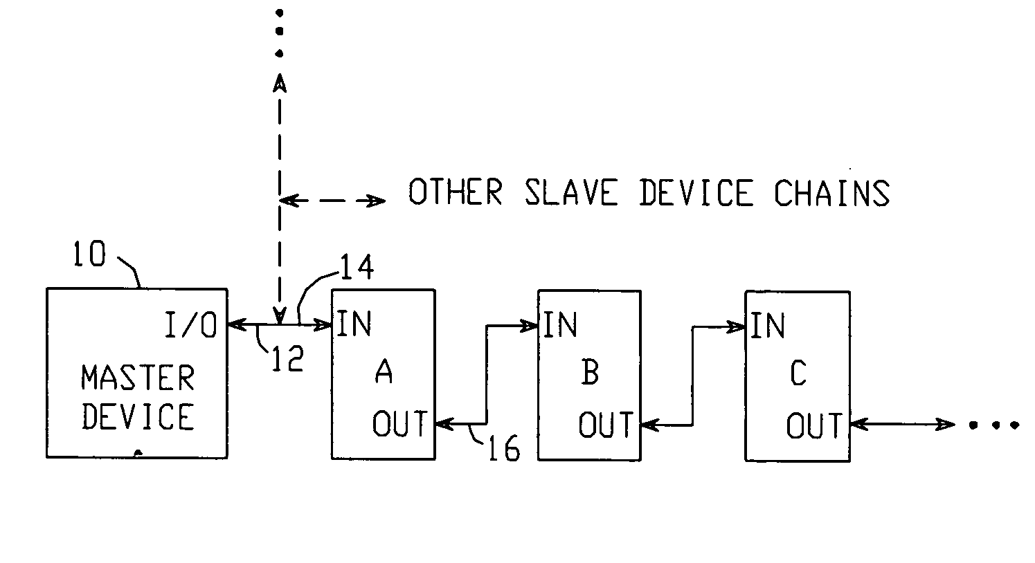
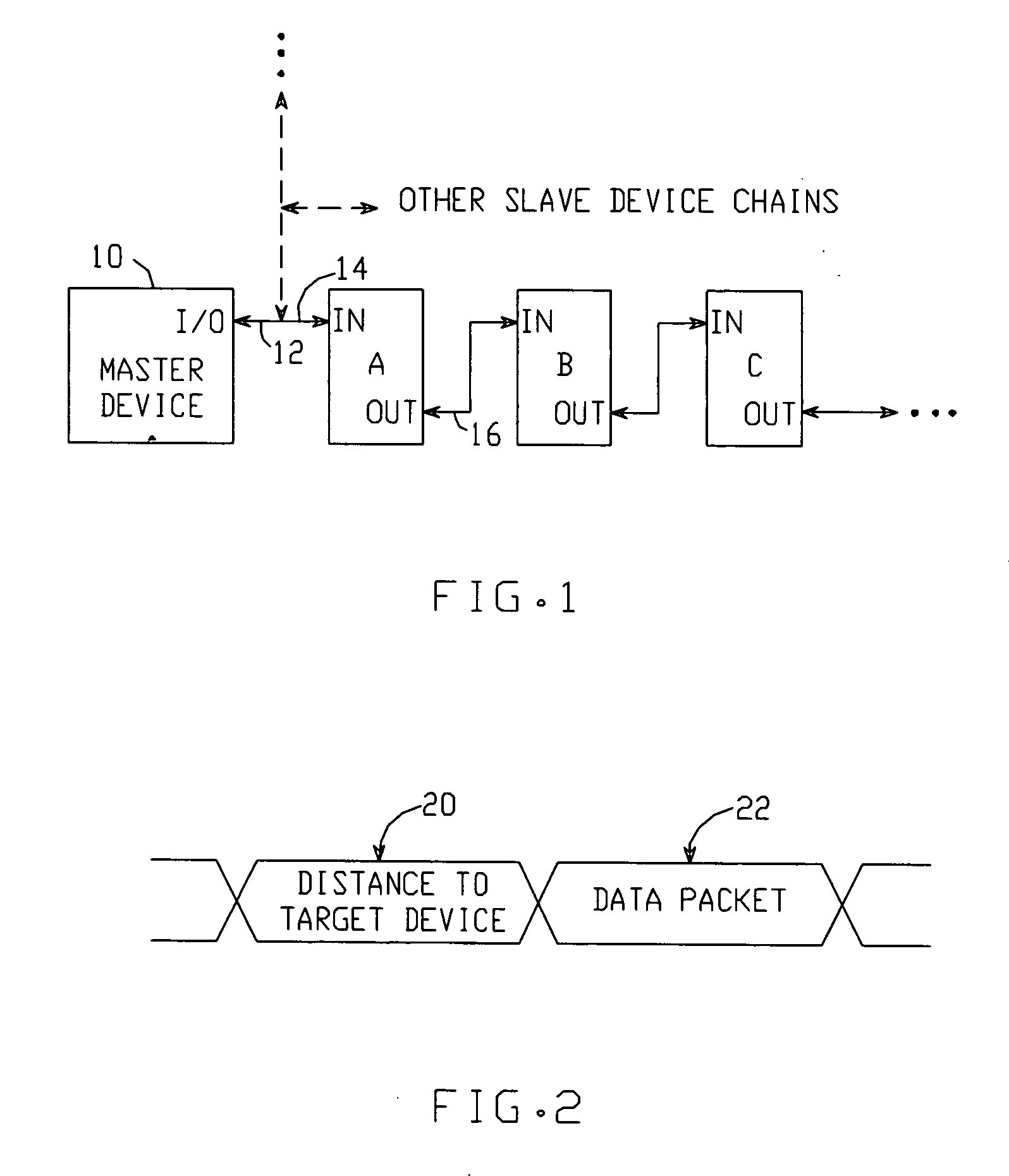
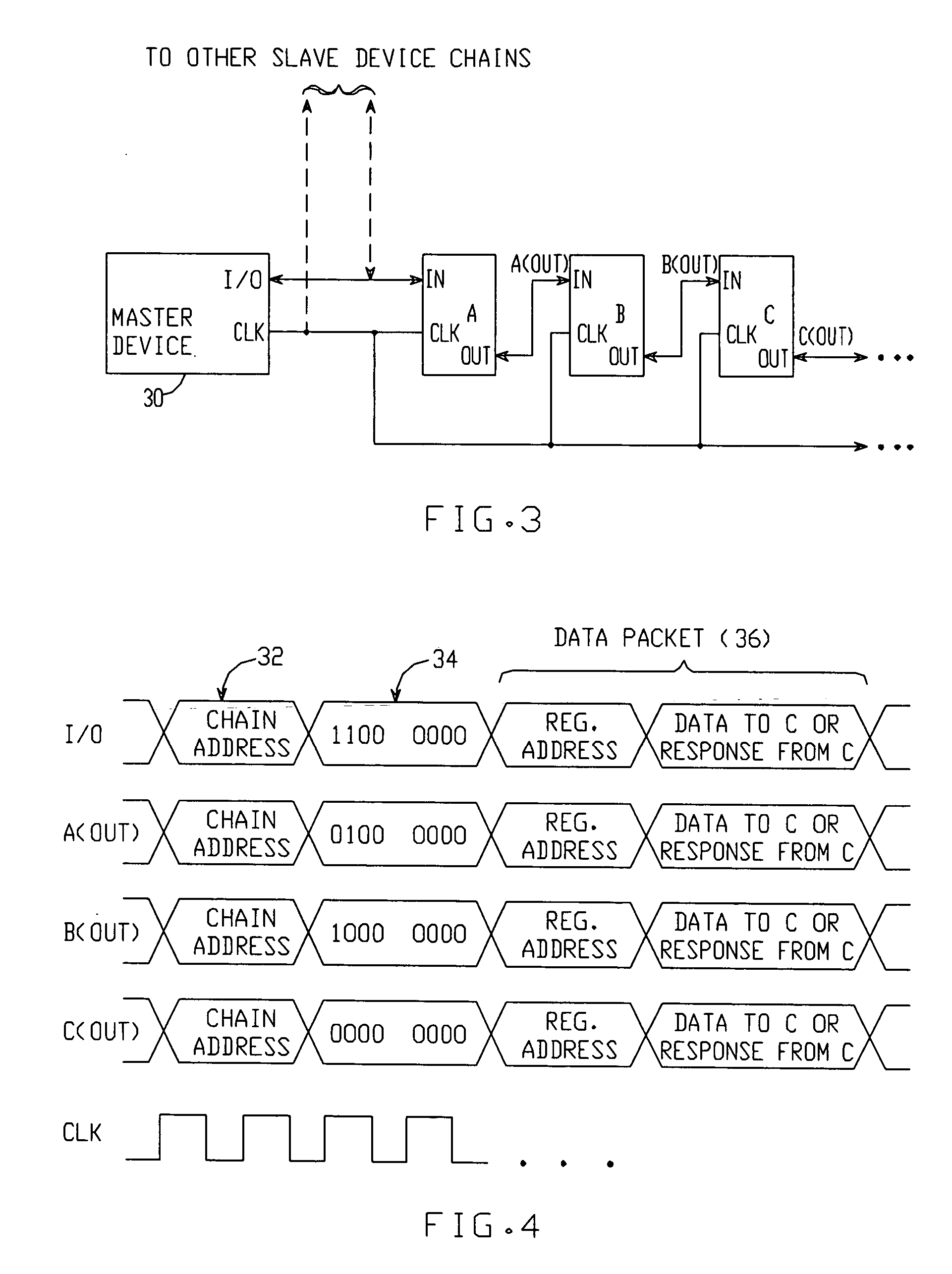
The present invention is a system and method for serial digital communication that overcomes the problems of previous systems. The system requires only one wire and does not require an address for any of the devices. The master device sends and receives messages to and from a chain of serially-connected slave devices. Each slave device has two nodes, and the first node of each slave device is connected to the master device's I / O node. The master device sends a message with a value that represents the distance between the master device and the target slave device, and the data to be conveyed between the master device and the target device. Each slave device receives the message, determines if it is the target device, and either increments or decreases the distance value. The data is then passively buffered back to the master device with no latency. The system can communicate with multiple slave device chains, and each chain can be identified by the target device. The technical effects of this invention include improved speed, reliability, and efficiency of serial digital communication.

Problems solved by technology

This can be expensive, as it requires each device to have the necessary hardware interface (e.g., dedicated I / O pins on the device).
These costs can be unacceptably high, particularly for simple devices that would otherwise be small and inexpensive.
However, the SPI requires that each interconnected device have a pin by which the device is enabled prior to transferring data; this increases processing overhead and the system's I / O requirements.
The system also requires 4 wires, which may consume more area than is desired.

Method used


Image

  • Serial digital communication system and method
  • Serial digital communication system and method
  • Serial digital communication system and method

Examples


Embodiment Construction

[0025] A serial digital communication system per the present invention is shown in FIG. 1. A master device 10, such as a microprocessor or microcontroller, has an input / output (I / O) node 12 for sending and receiving messages to and from one or more ‘slave’ devices. The slave devices (device A, device B, device C, . . . ) are serially connected to form a chain. Each slave device has at least a first node (14) and a second node (16): the first node 14 of the first slave device in the chain (device A) is connected to the master device's I / O node 12, and the second node of each slave device is connected to the first node of the subsequent slave device in the chain. Though the first and second nodes are labeled “IN” and “OUT”, respectively, each preferably operates bi-directionally—i.e., the master and slave devices are preferably arranged such that each node supports bi-directional communication.

[0026] The master device is arranged to originate messages, each of which is intended for a...


PUM


Abstract

A communication system includes a master device which communicates with a chain of serially-connected slave devices. The master originates messages, each of which is intended for a particular ‘target’ slave device. Each message contains a ‘distance to target device’ value equal to the number of devices between the master and target, and a data packet containing data to be conveyed between the master and target. Each slave device determines if the ‘distance to target device’ value indicates that it is the target. If not, the slave device increments or decrements the value in real time, with no latency, and transmits the modified message to the next slave device until received by the target device. In one embodiment, the target device may place data in the data packet, and the slave devices are arranged to buffer the data back to the master device.

Description

[0001] This application claims the benefit of provisional patent application No. 60 / 556,817 to Daly et al., filed Mar. 24, 2004.BACKGROUND OF THE INVENTION [0002] 1. Field of the Invention [0003] This invention relates to the field of digital communication systems, and particularly to addressing schemes for such systems. [0004] 2. Description of the Related Art [0005] Many systems exist for transferring data between peripheral devices and a master device such as a microprocessor. Such systems typically employ a multiple-wire bus structure to which each device is connected, with data transferred between devices either serially or in parallel. To retrieve data from a particular device on the bus, the device must first be addressed or enabled in some fashion. Systems of this type include the SMBus and i2c bus systems. [0006] However, such systems require each device to have a unique address or unit number that is configured in hardware. This can be expensive, as it requires each device...

Claims


Application Information

Patent Timeline
Patent Type & Authority Applications(United States)
IPC IPC(8): G06F13/00G06F13/42
CPCG06F13/4256
Inventor DALY, MICHAEL P.AUDY, JONATHAN M.
Owner ANALOG DEVICES INC
Learn More