Paintball gun loading device

Inactive Publication Date: 2005-10-06
SUNWORLD INDAL
View PDF5 Cites 5 Cited by
  • Summary
  • Abstract
  • Description
  • Claims
  • Application Information

AI Technical Summary

Benefits of technology

[0005] It is the primary objective of the present invention to provide a paintball gun loading device, which is easy and quick to install.
[0006] It is another objective of the present invention to provide a paintball gun loading dev

Problems solved by technology

The connection between the loading member B and the gun A may cause

Method used


Image

  • Paintball gun loading device
  • Paintball gun loading device
  • Paintball gun loading device

Examples


Embodiment Construction

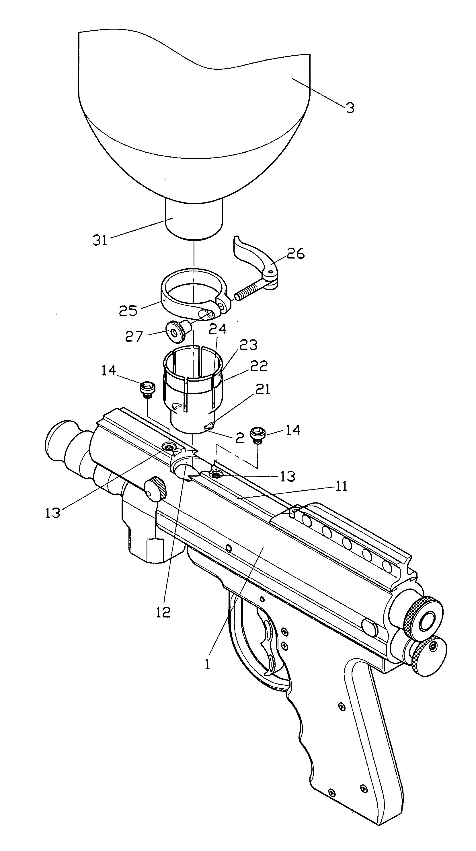
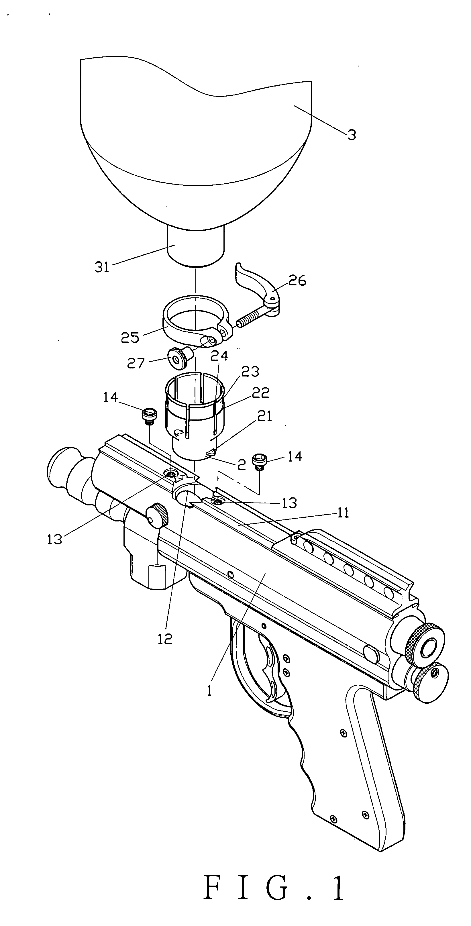
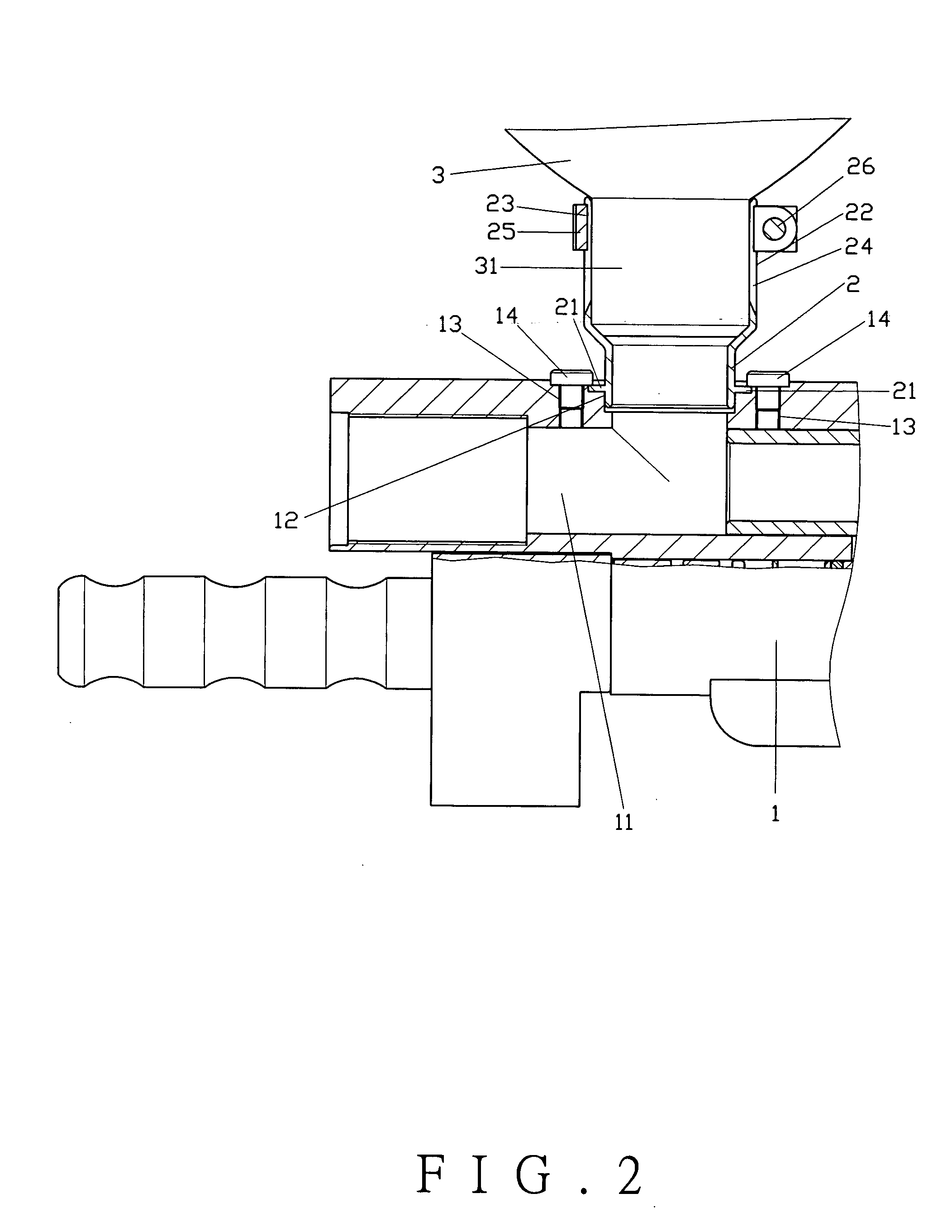
[0013] As shown in FIG. 1, the present invention comprises a gun body 1, a loading member 2, and a funnel 3.

[0014] The gun body 1 comprises an opening 12 on its barrel 11, and a pair of threaded holes 13 at respective sides of the opening 12 for a pair of screws 14 to thread therein.

[0015] The loading member 2 is secured to the opening 12 of the barrel 11 with a pair of lugs 21 at respective sides. The upper portion of the loading member 2 has a fixture 22 with a circular trough 23 thereat. A number of slots 24 are formed along the circular trough 23. A clamp 25 is adapted to sleeve on the circular trough 23 by means of a quick-release rod 26 and a nut 27.

[0016] The funnel 3 adapted to load with paintballs is secured to the fixture 22 of the loading member 2, and comprises a fixing end 31 at the bottom thereof.

[0017] To assemble the present invention, the lugs 21 of the loading member 2 are aligned with the two threaded holes 13 of the gun body 1 and secured with the screws 14. ...


PUM


Abstract

A paintball gun loading device includes a gun body, a loading member and a funnel. The loading member comprises a fixture at an upper portion thereof. The fixture comprises a circular trough with a plurality of slots along the circular trough. A clamp sleeved on the circular trough is tightened with a quick-release rod and a nut to fasten the funnel in a different size.

Description

BACKGROUND OF THE INVENTION [0001] 1. Field of the Invention [0002] This invention relates to a paintball gun loading device, and more particularly to a paintball gun able to replace with different sizes of funnels in a quick and easy manner. [0003] 2. Description of the Prior Art [0004] There are various paintball guns on the market, and the loading methods are different with each other. One conventional paintball gun A, as shown in FIG. 5, comprises an opening A2 at the top of a barrel A1, and a pair of threaded holes A3 at respective sides of the opening A2. The threaded holes A3 are inserted with a pair of screws A4 to secure protruding plates B 1 of a loading member B. The loading member B comprises a loading opening B2 on top thereof to connect with a fixing end C1 of a funnel C. This design allows the paintball to drop into the barrel A1 and wait for shooting. The connection between the loading member B and the gun A may cause loosening or misalignment, thus it has to be adju...

Claims


Application Information

Patent Timeline
IPC IPC(8): F41B11/00F41B11/02
CPCF41B11/52
Inventor YEH, KEN-CHIN
Owner SUNWORLD INDAL
Why Eureka
Try Eureka