Off road vehicle

a technology for vehicles and vehicles, applied in the field of off-road vehicles, can solve the problems of fuel waste, two steering systems clashing, and scuffing of the ground traversed,

Inactive Publication Date: 2005-10-06
SPARK IAN JAMES
View PDF0 Cites 56 Cited by
  • Summary
  • Abstract
  • Description
  • Claims
  • Application Information

AI Technical Summary

Benefits of technology

[0026] The preferred means of driver control of the four wheel steering / flour wheel drive variant of the previously proposed invention is by means of a rotatable joystick. This maximises the manoeuvrability of the vehicle by allowing independent translation and rotation of the vehicle. In this means of driver control, the direction of translation of the vehicle is determined by the direction of displacement of the joystick, whereas the rotation of the vehicle is determined by the degree of rotation of the joystick. The amount of displacement of the joystick determines the root mean square of the four wheel speeds. Pure translation occurs when the joystick is displaced but not rotated. Pure rotation occurs when the joystick is twisted as far as it will go.

Problems solved by technology

In general these two steering systems will conflict with one another when each tries to achieve a different centre of curvature for the path of the vehicle.
This conflict causes a braking effect, which results in fuel wastage, scuffing of the ground traversed and associated tyre wear.
Unfortunately, making one steering system compliant with the other leads to stability and traction problems when the vehicle is operated in difficult conditions.
If the sideways, forwards or backwards force on the vehicle increases and / or the coefficient of friction between the tyres and the ground decreases, the system used to manoeuvre the vehicle will eventually fail.
In this environment weight is transferred from the uphill drive wheel making it liable to spinning.
Although the stability of the traditional tractor can be improved by the use of a limited slip differential or a lockable differential, it is somewhat illogical to provide a differential in the first instance along with a subsidiary system which either impedes its operation, or stops it altogether.
Because these castors cannot exert any sideways force on their end of the vehicle, the tendency for this end to swing down the hill can only be prevented by the two drive wheels applying opposing forces to the vehicle—even though they may be driven at the same speed.
As the steepness of the slope traversed increases, the uphill drive wheel eventually loses traction and the front of the vehicle swings down the hill.
This method of manoeuvring causes extreme scuffing with associated ground damage, fuel wastage and tyre or track wear.
As a consequence, rotation and translation in a confined space can be a problem.
However these applications do not take into account either the slip angles of the tyres or the longitudinal slip of these tyres.

Method used


Image

  • Off road vehicle
  • Off road vehicle
  • Off road vehicle

Examples


Embodiment Construction

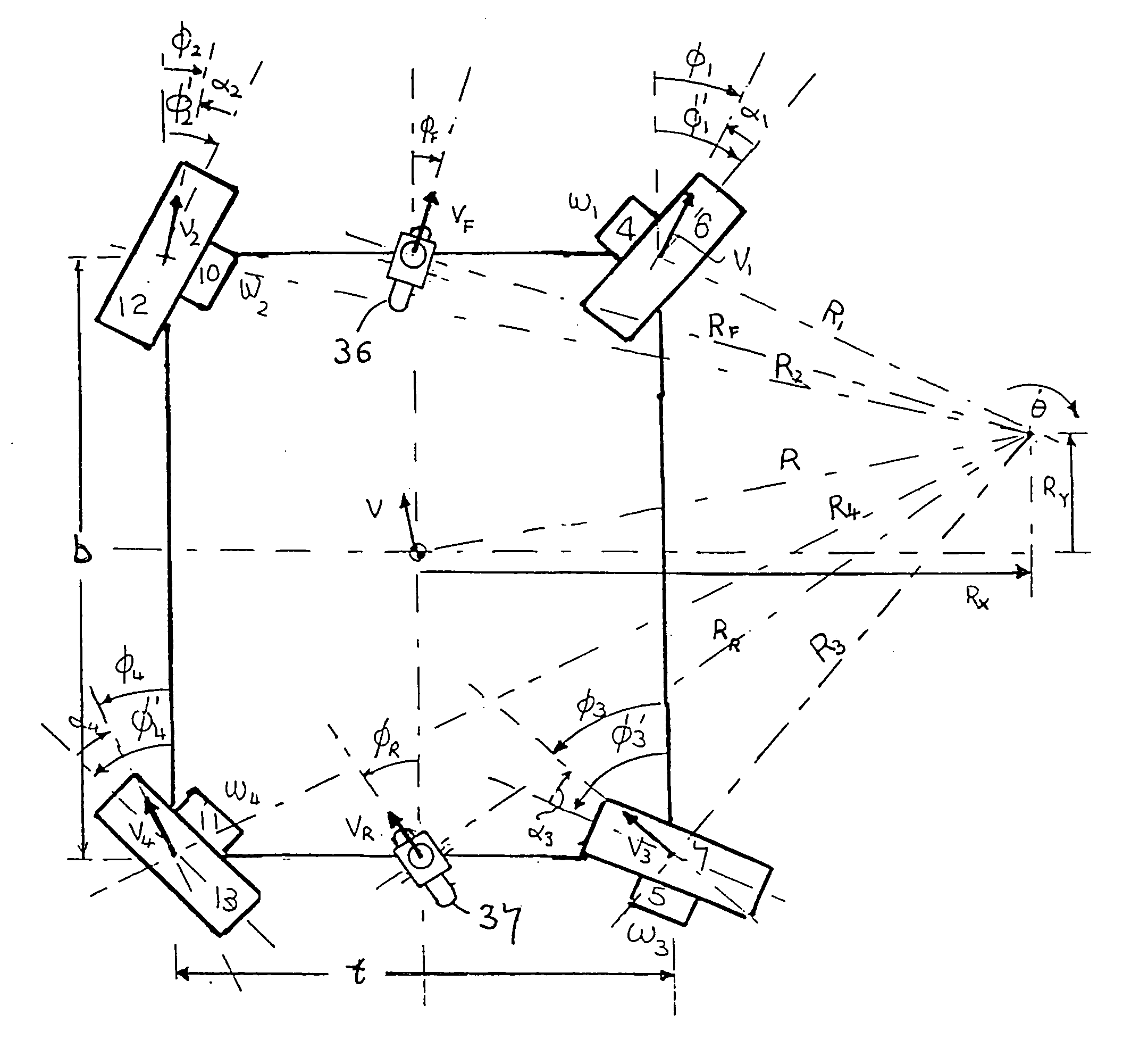
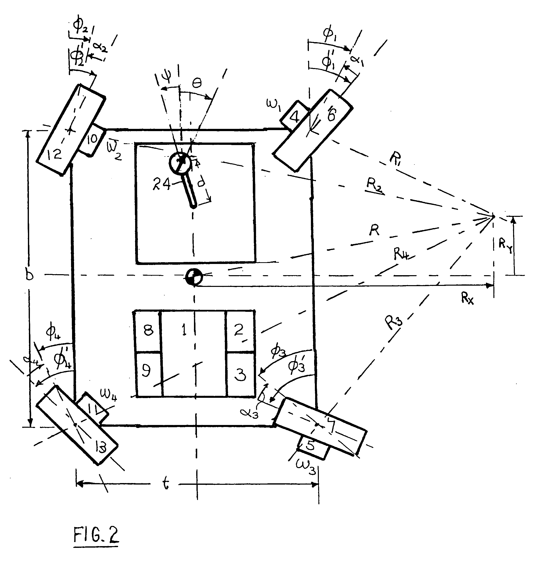
[0062] In the four wheel steering / four wheel drive variant of the invention depicted in FIG. 2, an internal combustion engine 1 drives two right hand variable displacement hydraulic pumps 2 and 3 which in turn drive hydraulic motors 4 and 5 mounted in the steerable front and rear right hand wheels respectively. The internal combustion engine 1 also drives left hand variable displacement pumps 8 and 9 which in turn drive hydraulic motors 10 and 11 which are mounted in the steerable front and rear left hand wheels 12 and 13 respectively.

[0063] The effective angles of the wheels 6, 12, 7 and 13 are shown as φ1, φ2, φ3 and φ4 respectively. The effective rotational speed of the wheels 6, 12, 7 and 13 are ω1, ω2, ω3 and ω4 respectively.

[0064] The driver controls the vehicle by selecting the radius of curvature of the vehicde's path and the sense of rotation by rotating the joystick 24. If the joystick 24 is not turned the radius of curvature of the path of the vehicle will be infinity a...


PUM


Abstract

The invention describes vehicles where the steering effect of the driver-selected wheel angles is made identical to the steering effect of positively and independently driving the driven wheels. A method of compensating for the linear portions of the slip angles of all wheels and the linear portions of the longitudinal slip of the driven wheels is described where the slip angles and longitudinal slips are deduced from the forces acting on the wheels. Methods of measuring the slip angles and longitudinal slips of all wheels by means of two dummy castors are also described. Vehicles where the steering effect of the driver-selected wheel angles is made identical to the steering effect of positively and independently braking all wheels are also described. Means of applying the above principles to vehicles with either hydrostatic or mechanical drives are also described, including simplified vehicles with only two steerable wheels.

Description

TECHNICAL FIELD [0001] The invention relates to a means of increasing the tractability, stability, manoeuvrability and safety of wheeled vehicles while at the same time minimising fuel consumption d damage to the ground traversed. DESCRIPTION OF PRIOR ART [0002] The following patents or patent applications allude to the problem to be solved by the present invention, but do not go far enough to describe a complete solution. [0003] WO 98 / 19875 A1 (GRANT, publication date 14 May 1998) merely states that the drive wheel speeds and angles are calculated by a computer. [0004] WO 00 / 32462 A1 (Grant, publication date 19 Jun. 2000) describes equations for drive wheel speeds and wheel angles. These equations are hard to decipher since the variables are poorly defined. The equations for wheel speeds are clearly different from those described in the present invention, and as such must be incorrect. Grant's equations for wheel speed may approximate to the correct equations when the radius of cur...

Claims


Application Information

Patent Timeline
Patent Type & Authority Applications(United States)
IPC IPC(8): B60T8/24B62D1/12B62D7/15B62D9/00
CPCB60G2300/37B60T8/24B62D9/00B62D1/12B62D7/1509B60T8/246
Inventor SPARK, IAN JAMES
Owner SPARK IAN JAMES
Why Eureka
Try Eureka