Composite telephone pole

a telephone pole and composite technology, applied in the direction of pillars, buildings, structural elements, etc., can solve the problems of hazardous chemicals used as wood preservatives, and the design does not provide an adequate replacement for wooden utility poles

Inactive Publication Date: 2005-10-13
CADWELL CHARLES E +1
View PDF17 Cites 32 Cited by
  • Summary
  • Abstract
  • Description
  • Claims
  • Application Information

AI Technical Summary

Problems solved by technology

It is reported that the chemicals used as wood preservatives are known to be hazardous pesticides, yet are continuously used for wood utility poles.
As such, designs do not p

Method used


Image

  • Composite telephone pole
  • Composite telephone pole
  • Composite telephone pole

Examples


Embodiment Construction

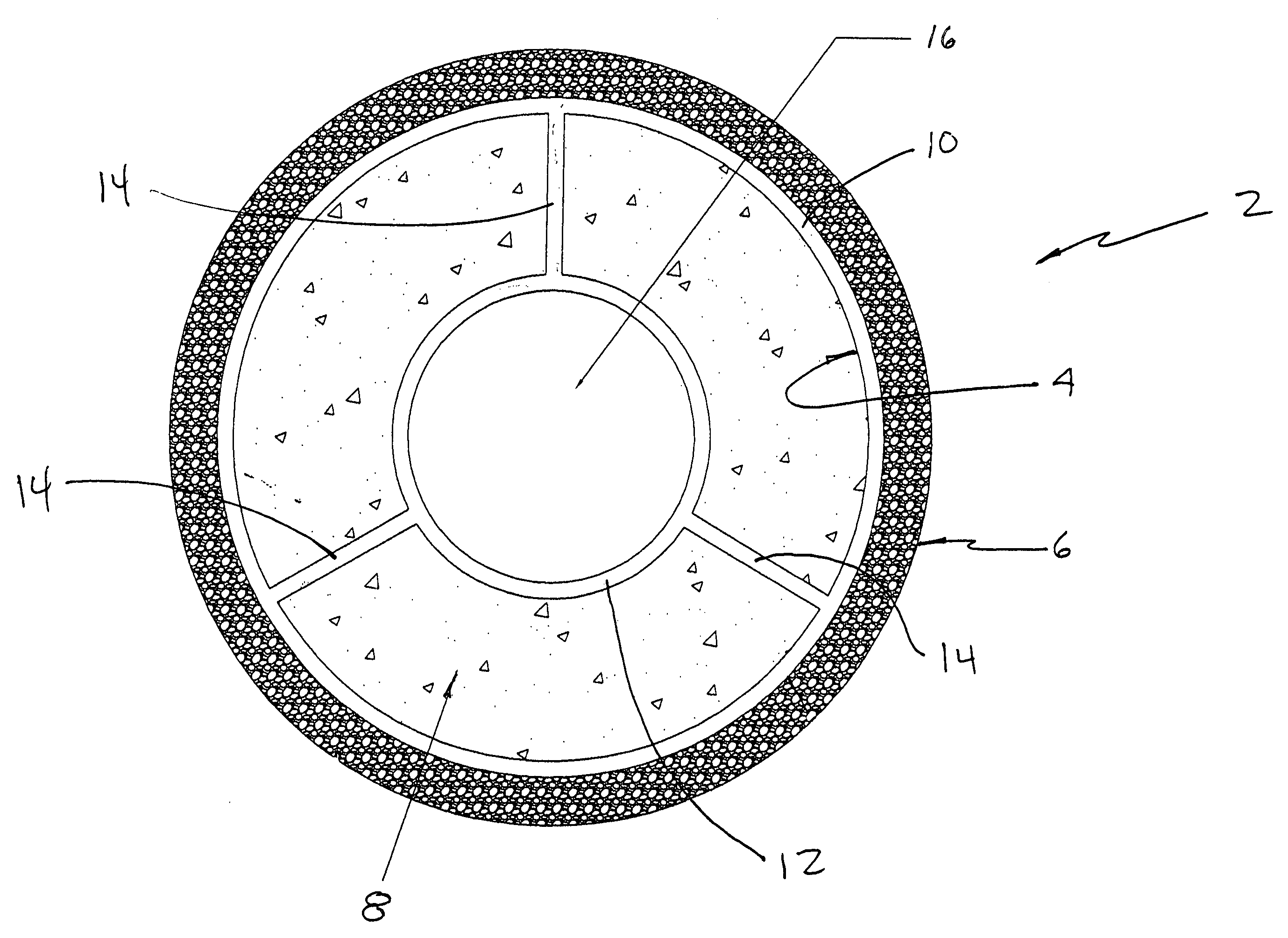
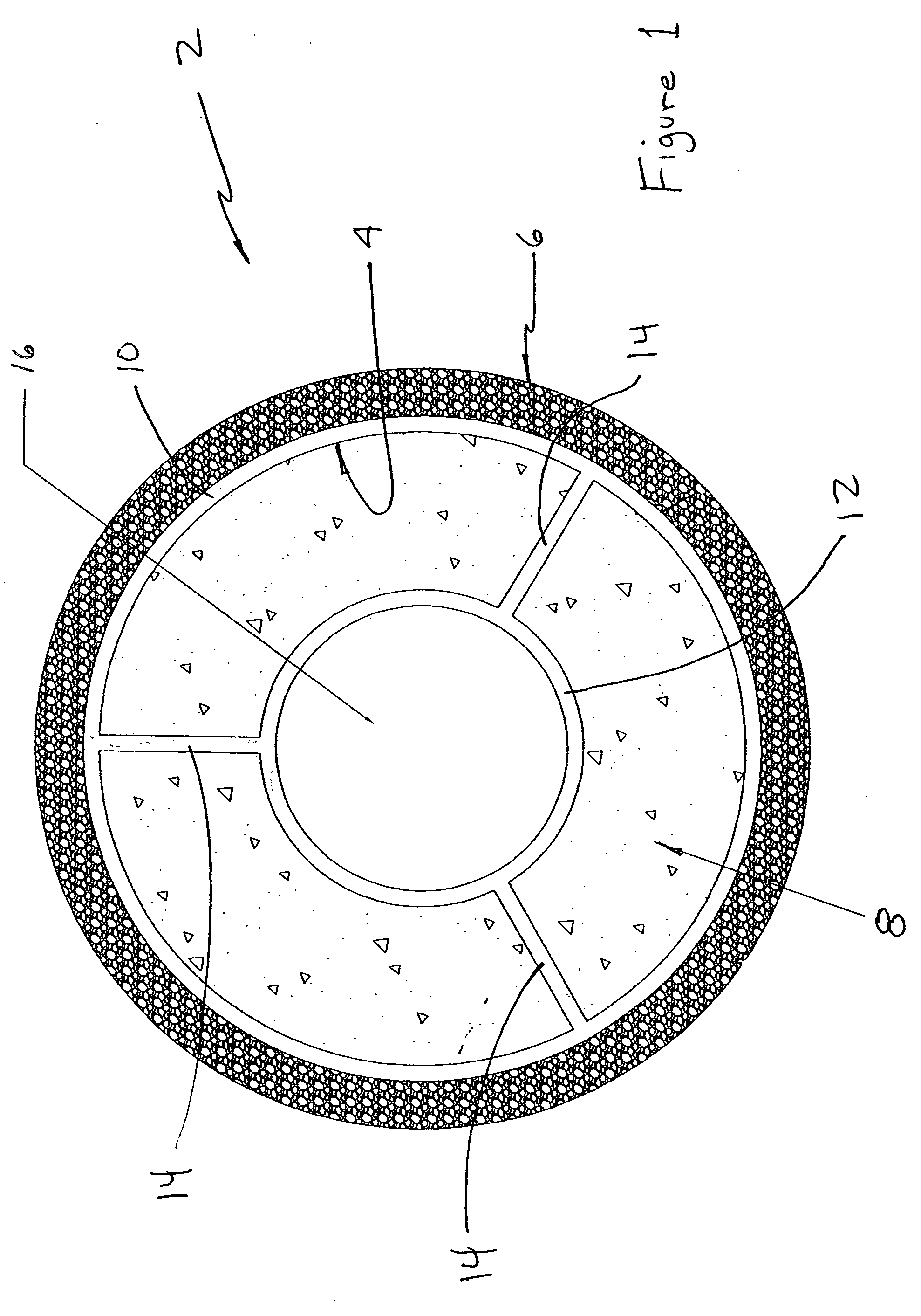
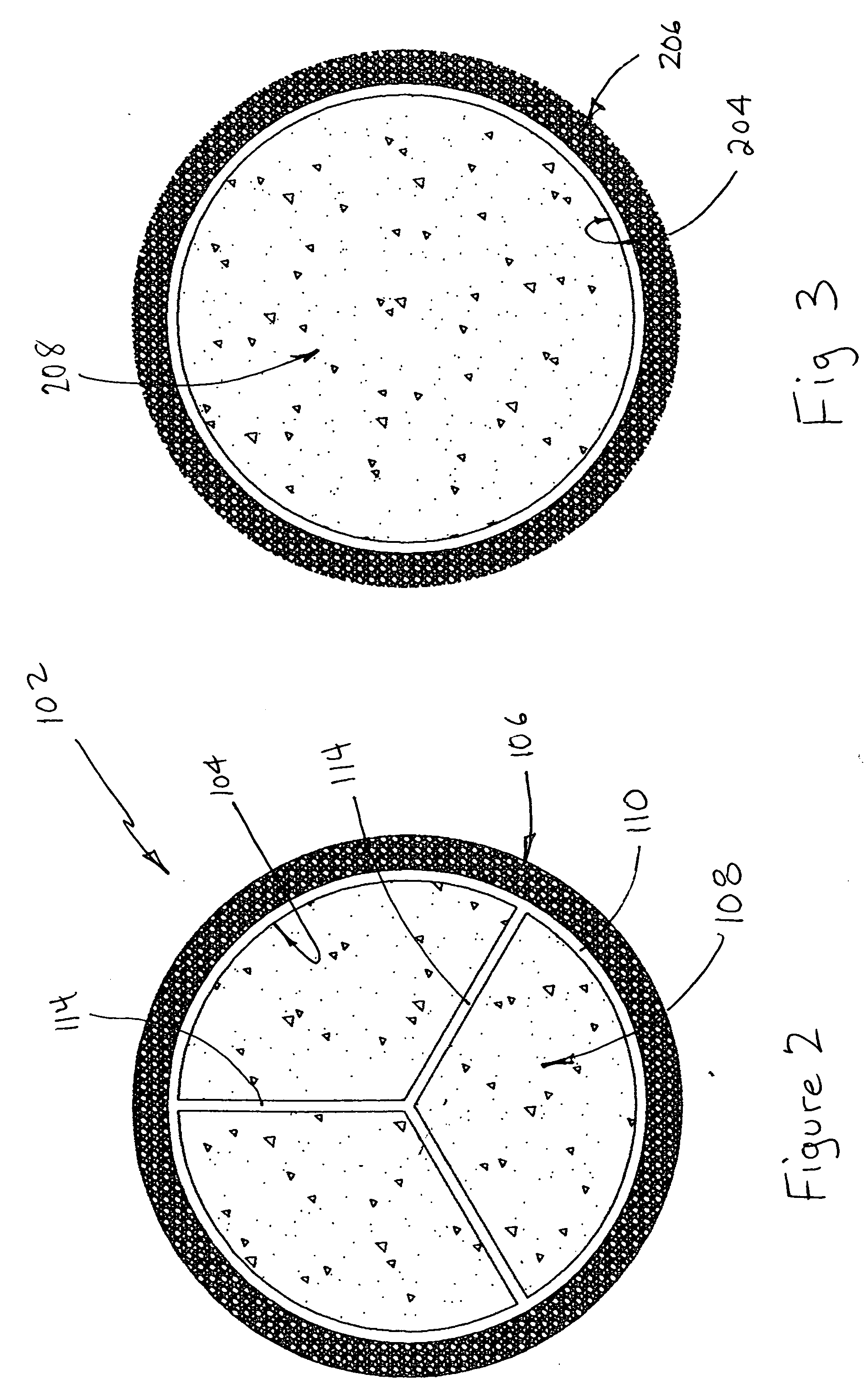
[0020] With reference first to FIG. 1, the composite tubular member is shown in cross section generally at 2, to include a structural elongate member 4 having an outer deformable composite material deposited thereon, shown best at 6 and, a strengthening material filling at least a substantial portion of the structural elongate member, shown at 8.

[0021] With reference still to FIG. 1, the structural elongate member 4 includes an outer tubular member at 10, an inner tubular member at 12, where the inner and outer tubular members are disposed substantially concentrically, and are held together by radially extending ribs 14. Thus, the structurally elongate member defines three ring-shaped volumes, defined within the confines of the inner and outer tubular members 12, 10 and intermediate the ribs 14, together with an inner volume 16 defined within the inner tubular member 12.

[0022] In the embodiment shown in FIG. 1, the three ring-shaped portions are filled with the strengthening mater...


PUM


Abstract

A composite utility pole or the like is shown, having an elongate member, where a deformable material is co-extruded over the outer surface. The elongate member can have any configuration, but is shown as a circular cross section, and can have structural ribs. Concrete fills the substantial portion of the pole to give it rigidity.

Description

BACKGROUND OF THE INVENTION [0001] The invention relates to a composite, preservative-free utility pole, such as a light or telephone pole. [0002] It is reported that the chemicals used as wood preservatives are known to be hazardous pesticides, yet are continuously used for wood utility poles. It is estimated that 135,000,000 such poles are in use in the United States. See “Poison Poles” 1997 Report by the National Coalition Against the Misuse of Pesticides (NCAMP). In another NCAMP report, “Pole Pollution,” a 1999 report, it is reported that pentachlorophenol, or “penta,” is a known carcinogen, but is still used in the U.S. for chemically treated wood utility poles. At the same time, penta is banned in 26 other countries. [0003] For this reason, composite utility poles have been suggested in the prior art. For example, in Farber, U.S. Pat. No. 5,513,477, premolded external segments are suggested, which are combined in modular fashion for on-site assembly. Mirmiran et al. shows in ...

Claims


Application Information

Patent Timeline
IPC IPC(8): E04C3/34E04H12/02E04H12/12
CPCE04C3/34E04H12/02
Inventor CADWELL, CHARLES E.FISCHER, CARL
Owner CADWELL CHARLES E
Why Eureka
Try Eureka