Apparatus for decorating stiff objects by screen printing

Inactive Publication Date: 2005-10-13
KBA KAMMANN
View PDF4 Cites 14 Cited by
  • Summary
  • Abstract
  • Description
  • Claims
  • Application Information

AI Technical Summary

Benefits of technology

[0006] An object of the present invention is to design an apparatus for decorating inherently stiff objects by scr

Problems solved by technology

Furthermore, in many cases it was found that that apparatus was not able to satisfy the requirements, which are usually imposed nowadays in terms of the quality of the decoration or printed image produced on the respective objects.
That mode of operation admittedly means that the screen printing stencil takes up a small amount of space, but in this case the residence time of each re

Method used


Image

  • Apparatus for decorating stiff objects by screen printing
  • Apparatus for decorating stiff objects by screen printing
  • Apparatus for decorating stiff objects by screen printing

Examples


Embodiment Construction

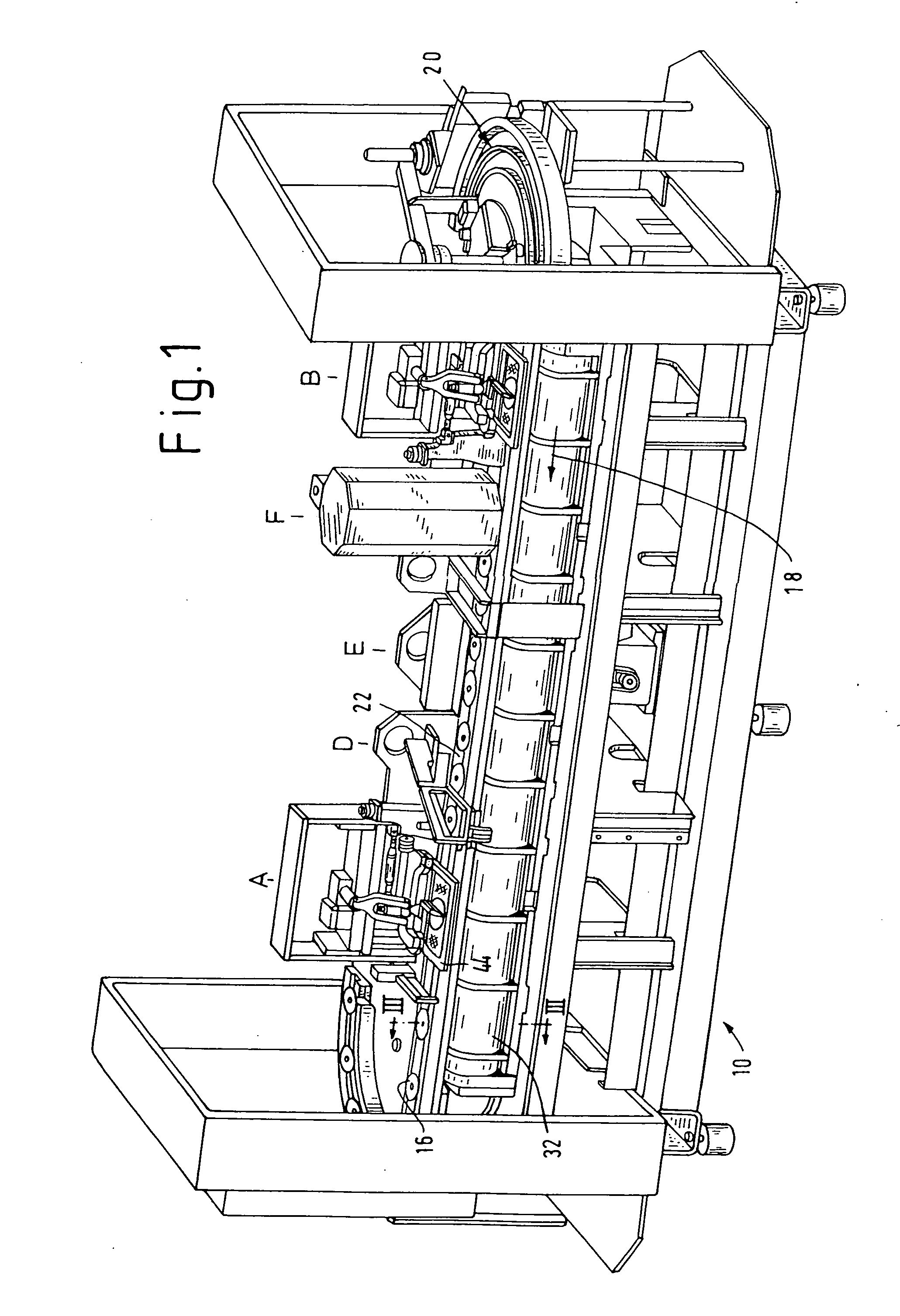
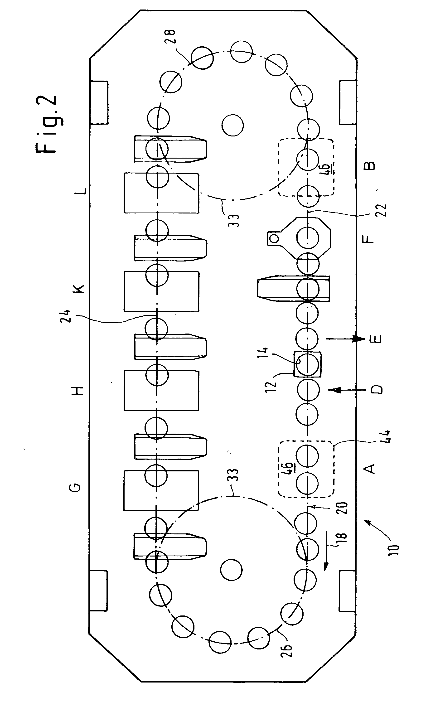
[0031] Reference will first be made to FIGS. 1 and 2 showing the fundamental structure of an apparatus for decorating inherently stiff objects using at least the screen printing process, in the form of a printing machine indicated generally at 10 which serves for applying printing to flat objects, for example CDs as illustrated here, or credit cards or similar articles.

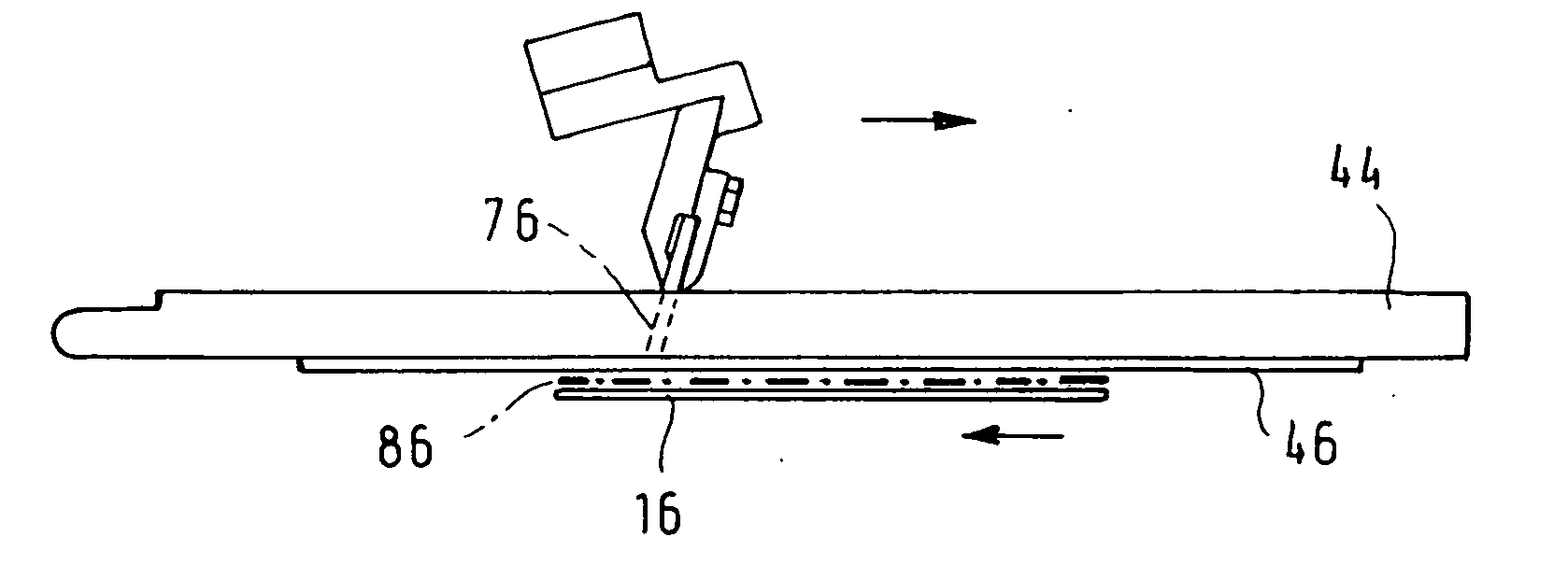
[0032] The machine 10 has a plurality of object carriers 12 which are in the form of carriages and each of which is provided on its top side with a receptacle indicated at 14 in FIGS. 2 and 3, for an object indicated at 16 for example in FIG. 1. The object carriers 12 are movable in the direction of the arrow 18 in FIG. 1, along a transport path identified by reference 20 in FIGS. 1 and 2. The transport path 20 comprises two linear portions 22, 24 arranged at a horizontal spacing from each other and two substantially semicircular portions 26, 28 which interconnect the two linear portions 22, 24.

[0033] Associated wit...


PUM


Abstract

In an apparatus for decorating stiff articles using a screen printing process, an object carried by an object carrier and the stencil are advanced synchronously along a transport path during a printing operation. A doctor co-operable with the stencil is movable in an opposite relationship to the direction of movement of the stencil and the object. In the region of the at least one screen printing station is a transport screw with at least one screw flight as a drive for the object carrier, which is in engagement with the screw flight of the screw. During a printing operation the object carrier with object, on the one hand, and the stencil, on the other hand, pass synchronously through an acceleration phase and a deceleration phase. The printing stroke of the stencil is less than the total stroke thereof in the direction of movement of the object carrier.

Description

BACKGROUND OF THE INVENTION [0001] The invention concerns an apparatus for decorating stiff objects by screen printing. [0002] A form of apparatus for decorating, such as printing, inherently stiff objects using screen printing provides that, during the decorating or printing operation, the object to be printed upon is carried by an object carrier. The object on the carrier and at least one screen printing stencil are advanced synchronously along a transport path while a doctor co-operable with the stencil is movable in an opposite relationship to the direction of movement of the object and the stencil. Thus, an apparatus of that nature, which is to be found for example in German published patent application DE-OS 24 02 386, provides that the carrier and the object carried thereby are moved during the transport phase and also during the printing phase on a double chain which circulates in a vertical plane at a constant speed. [0003] Although that apparatus represented a significant ...

Claims


Application Information

Patent Timeline
IPC IPC(8): B41F15/08B41F15/14B41F15/18B41F15/42B41F15/44B41F17/00B41M1/12B65G33/02F16H25/20
CPCB41F15/423B41P2217/55
Inventor STEFFEN, VOLKERHEIDENREICH, HORST
Owner KBA KAMMANN
Why Eureka
Try Eureka