

Assembly for a seat frame, seat frame and method for manufacturing such an assembly
- Summary
- Abstract
- Description
- Claims
- Application Information
AI Technical Summary
Benefits of technology
Problems solved by technology
Method used
Image

Examples
Embodiment Construction
[0038]In the following description, when reference is made to absolute position qualifiers, such as the terms “before,”“behind,”“top,”“bottom,”“left,”“right,” etc., or relative position qualifiers, such as the terms “above,”“below,”“superior,”“inferior,” etc., or to orientation qualifiers, reference is made to a seat in a normal position of use in the ordinary direction in which the vehicle progresses.
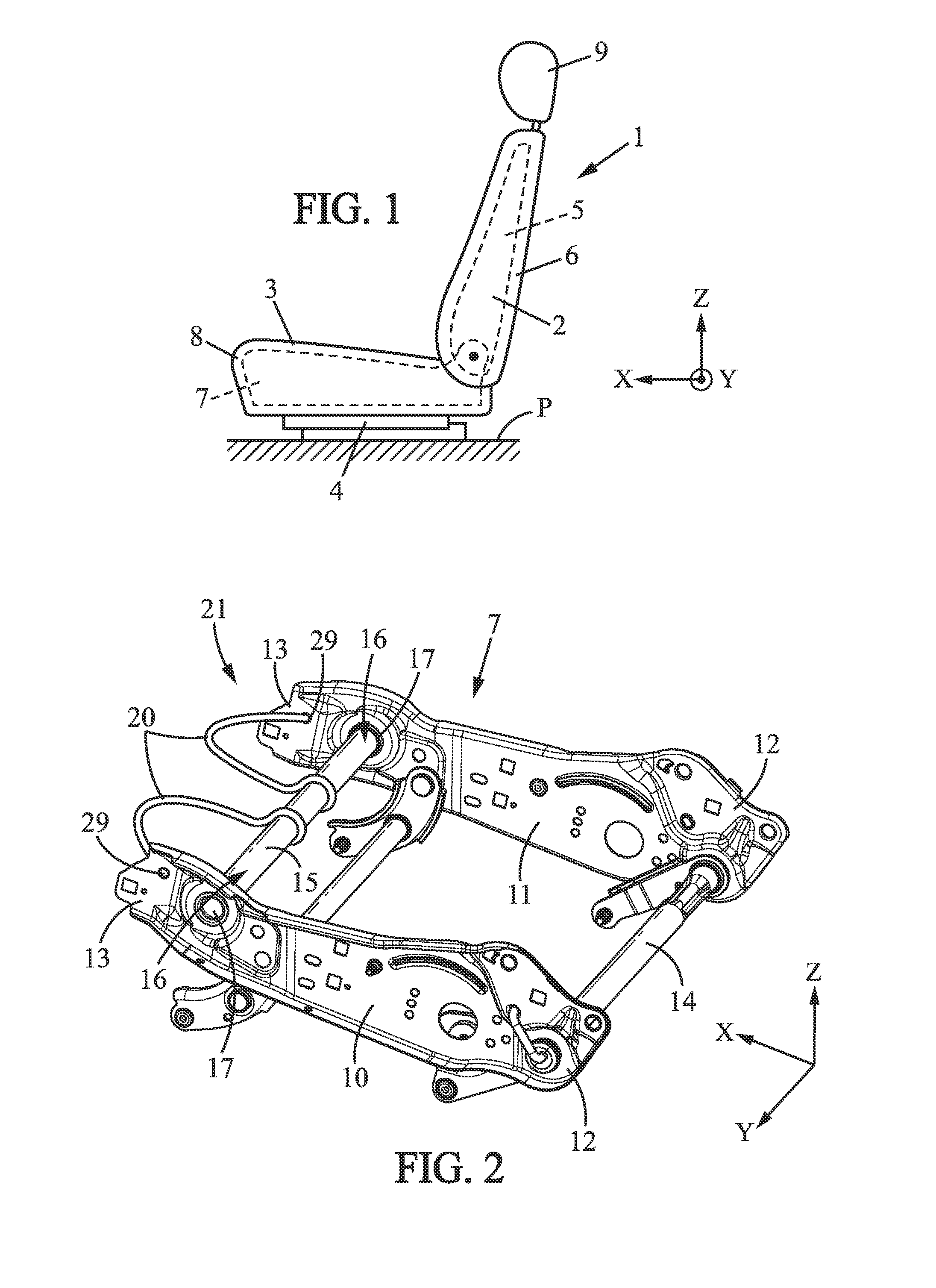
[0039]FIG. 1 represents a schematic view of a seat 1 of an automobile according to an embodiment of the present invention comprising a backrest 2 and a seat portion 3 on which the backrest 2 may, for example, be mounted. Seat portion 3 may be fitted on a floor P of the automobile chassis through one or more slides 4, for example two side slides.
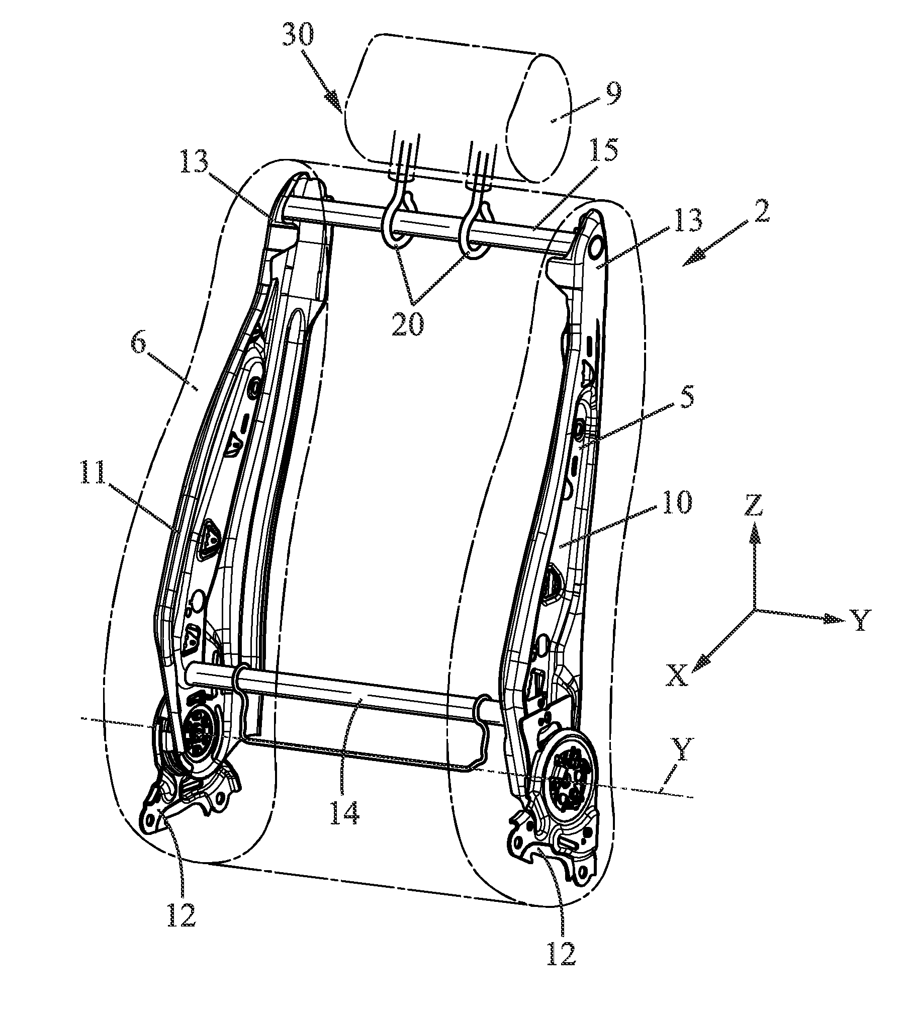
[0040]Backrest 2 comprises a backrest frame 5, preferentially rigid, on which a backrest cover 6 is mounted. Seat portion 3 comprises a seat portion frame 7, preferentially rigid, on which a seat portion cover 8 is mounted. Backrest frame 5 is m...
PUM
 Abstract
Description
Claims
Application Information