
System and method for ventilating a turbine

Inactive Publication Date: 2015-08-18
GE ENERGY PRODS FRANCE
View PDF9 Cites 2 Cited by
  • Summary
  • Abstract
  • Description
  • Claims
  • Application Information

AI Technical Summary

Benefits of technology

The invention aims to simplify ventilation systems and adapt to different air extraction flow rates while maintaining quiet operation and complying with environmental standards and directives. The pressure drop device and means of regulating air flow rate in the extraction duct allow for regulation of air flow rate based on the fan's output, keeping the air flow rate constant by 10% at most. Additionally, an end stop accessible from outside the duct allows easy regulation of the flap's maximum angle.

Problems solved by technology

As environmental standards and European directives are becoming increasingly tight, ventilation systems operating in an “explosive atmosphere” are subject to very strict regulations, dictating the design of such ventilation systems.
Moreover, leaks of gas in air extraction ducts may be due to potential leaks in the flanges of the pipework resulting from vibrations caused by the turbine or from thermal expansions due to excessive temperatures within the turbine.
In order to comply with environmental standards, the ventilation systems have become increasingly complex, through the addition of several motor driven fan units, providing redundancy, the disadvantage here being the increase in the size and weight of such systems and making on-site assembly and maintenance more difficult.
These valves are unable to seal the system completely and the frequent sticking of these valve shutters leads to air leaking between the fans, thus altering the flow and the profile of the ventilation.
The solutions proposed in the prior art are unable to offer a ventilation system capable of adapting to suit different air extraction flow rates.

Method used


Image

  • System and method for ventilating a turbine
  • System and method for ventilating a turbine

Examples


Embodiment Construction

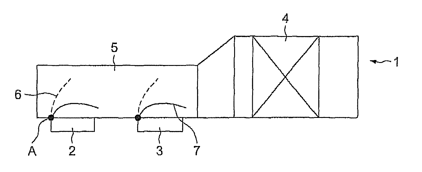
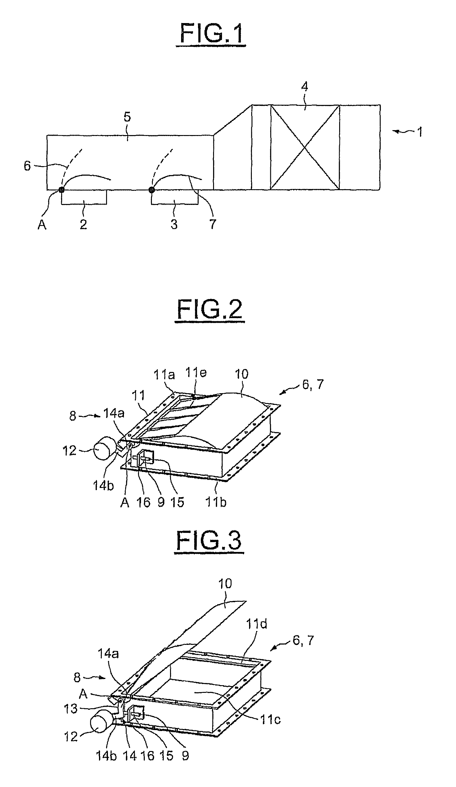
[0036]FIG. 1 schematically depicts a ventilation system 1 for a gas turbine.

[0037]Such a system is intended to provide ventilation for stationary parts of the turbine such as the spool or the stator of the turbine and for this purpose is intended to be connected in contact with the turbine.

[0038]It essentially comprises an air extraction duct 5 provided with a noise attenuating device 4, in this particular instance a silencer, and a set of fans 2 and 3, in this instance two of them, intended to inject air into the extraction duct 5.

[0039]The duct 5 is fitted to the compartment of the turbine that is to be ventilated and is thus used for renewing the air in the compartment, diluting and detecting any potential leaks of gas, and attenuating the nuisance noise generated by the extraction air flow along the duct 5.

[0040]With a view to regulating the extraction air flow rate, the system 1 is further provided with devices 6 and 7 for varying the pressure drop, which devices are positioned...


PUM


Abstract

This ventilation system (1), notably for a gas turbine, comprises at least one fan (2) opening into an air extraction duct (5).It comprises at least one device (6) for varying the pressure drop in the air extraction duct (5), comprising a means (8) of regulating the air flow rate in the air extraction duct (5).

Description

BACKGROUND OF THE INVENTION[0001](a) Field of the Invention[0002]The invention relates to ventilation systems for turbines.[0003]More specifically, the invention relates to a ventilation system capable of adapting to suit different air extraction flow rates.[0004]One particularly beneficial application of the invention relates to a ventilation system for a gas turbine.[0005](B) Description of the Related Art[0006]Gas turbines, particularly industrial turbines developing powers of between 40 and 130 megawatts, generally use ventilation systems in order to avoid thermal deformation in the spool or stator of the turbine.[0007]A ventilation system generally comprises at least one motor-driven fan and air inlet and extraction ducts connected to the turbine compartment. It also comprises a device for attenuating nuisance noise acting on the ventilation air inlet and extraction ducts.[0008]As environmental standards and European directives are becoming increasingly tight, ventilation syste...

Claims


Application Information

Patent Timeline
IPC IPC(8): F01D25/12F02C7/18F16K15/03F24F13/14F02C6/08F24F11/47F02K3/075F24F11/75
CPCF24F11/047F01D25/12F02C6/08F02C7/18F02K3/075F16K15/03F24F13/14F24F11/75
Inventor DOMINIAK, PASCALCOUDRIEEAU, JOELCARLES, PHILIPPE
Owner GE ENERGY PRODS FRANCE
Learn More