Inkjet cartridge cleaning devices

a technology for cleaning devices and inkjet cartridges, applied in printing and other directions, can solve the problems of inability to achieve cleaning techniques and prior art methods, and achieve the effects of restoring ink continuity to the print head, less suction power, and a large amount of suction

Inactive Publication Date: 2005-10-13
STRATITEC
View PDF36 Cites 1 Cited by
  • Summary
  • Abstract
  • Description
  • Claims
  • Application Information

AI Technical Summary

Benefits of technology

[0024] The two types of tips are able to work together, one after the other, in any order, to deliver suction cleaning of inkjet outlets in ways not accomplishable conventionally. The first tip having the smaller orifice will provide a greater amount of suction to one single port. This is most useful when trying to clean difficult clogs or impurities in the print head. The second tip may be used to clean all the ports simultaneously. Though it will deliver less suction power than the smaller tip, it can be used to restore ink continuity to the print head. By this it is meant that air bubbles may form in the print head. Especially after use of the smaller tip attachment. Air bubbles are sometimes formed by the use of the smaller tip. This is because, when ink is sucked out of one port, air will likely be simultaneously sucked into the unengaged ports. This happens because both the engaged and unengaged ports are all included in the same fluid system within the cartridge. The larger tip may, therefore, be used to correct the air-bubble problems presented by the more powerfully cleaning smaller tip. Thus, the two tips are likely to be used together to provide a thoroughly clean print head which is free of air as intended.

Problems solved by technology

This cleaning techniques, not possible with the prior art methods, use suction provided by a syringe.

Method used


Image

  • Inkjet cartridge cleaning devices
  • Inkjet cartridge cleaning devices
  • Inkjet cartridge cleaning devices

Examples


first embodiment

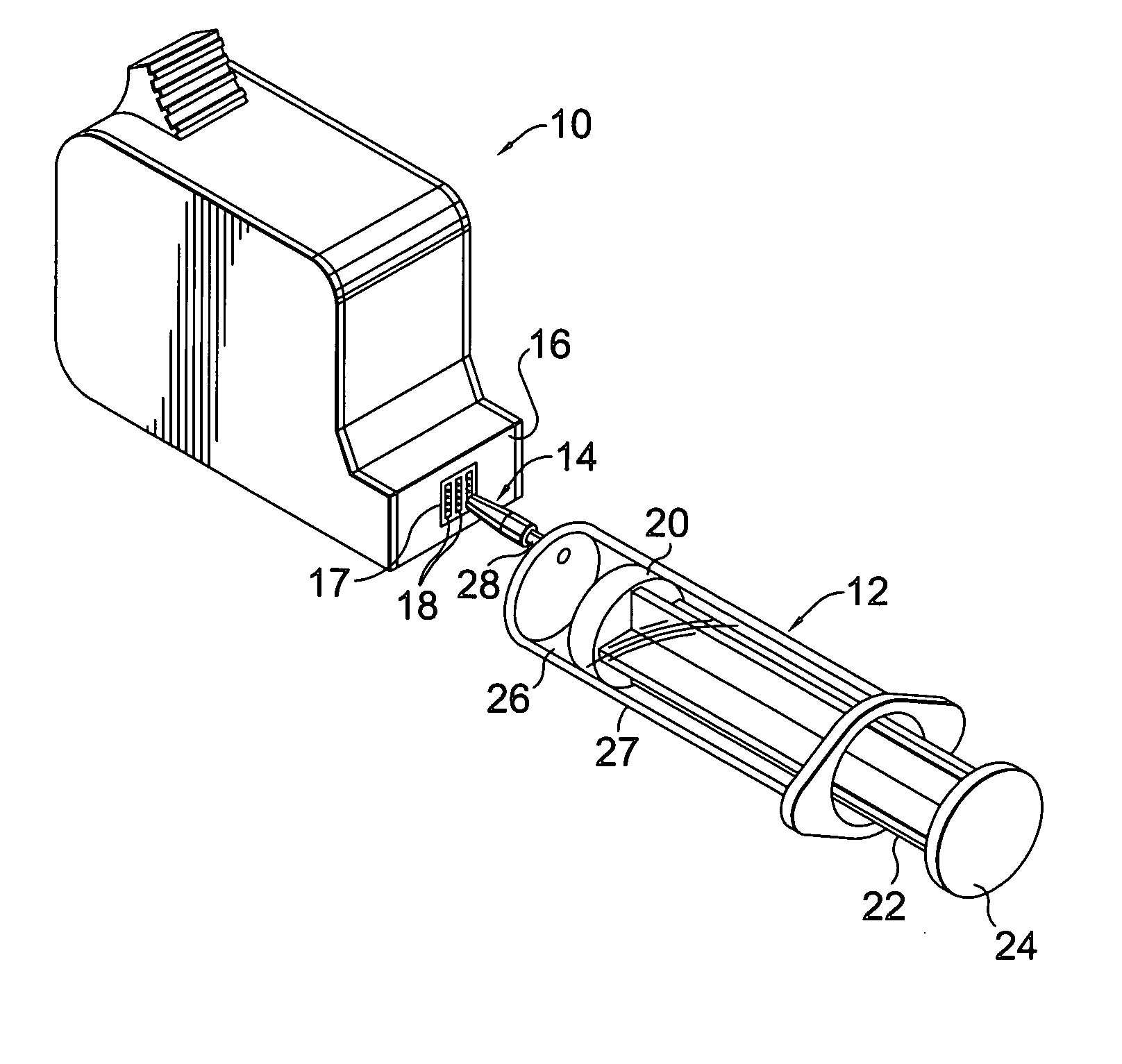
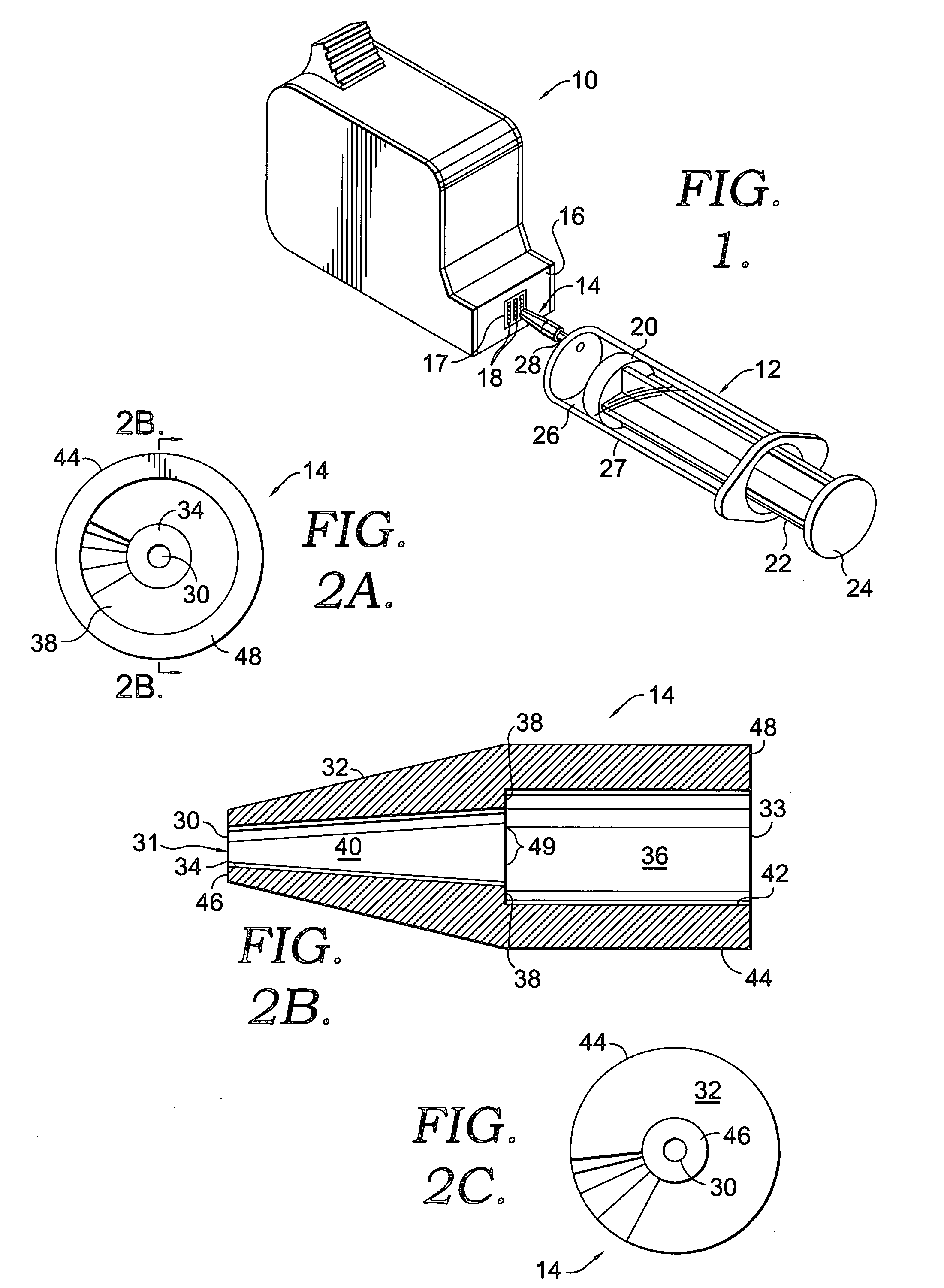
[0040]FIGS. 2A, 2B, and 2C show more details regarding the sealing member 14 of the invention. Member 14 has a forward end 31 and a rear end 33. At the forward end 31 of member 14 an aperture 31 is minimized. Its size is minimized so that it may deliver maximum suction force. Both an outside surface 32 and an inside surface 34 of the forward end 31 of member 14 are tapered, as can be seen in FIG. 2B. Surface 32 is tapered such that it can be easily inserted for filling purposes (as will be described hereinafter).

[0041] Inside tapered surface 34 is tapered such that the pressure created in conduit 40 is focused on a smaller cross-sectional area. In addition to maximizing the suction pressure administered to an individual port or small group of ports, through aperture 31, the taper also increases peripheral visibility of the printhead when targeting a particular port on the printhead for the application of suction.

[0042] At its rear end 33 member 14 includes a stem receiver 36 void. ...

second embodiment

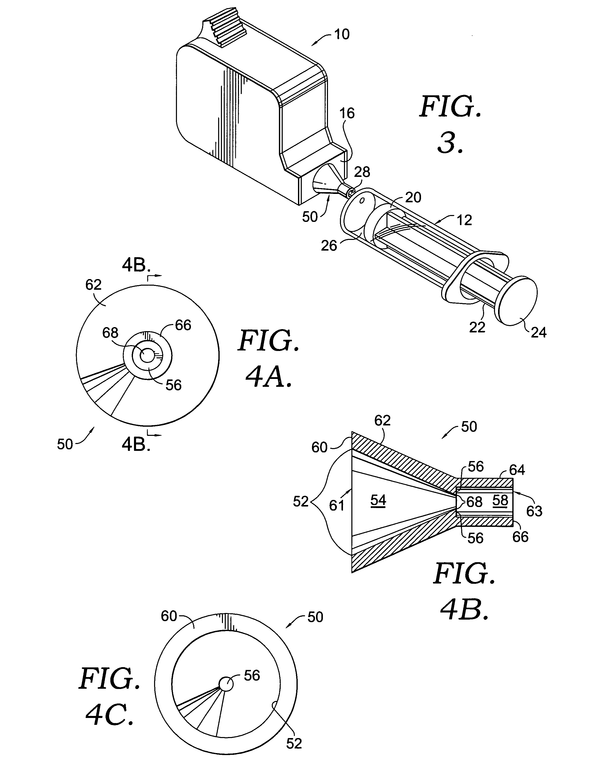
[0047] Referring to FIG. 3, we see that member 50 of the second embodiment covers a much greater surface area of the forward surface 16 of the print head 18. In fact, the entire print head 17 is covered by the suction cup like member 50.

[0048] Referring to FIGS. 4A-C, we see the details regarding the specific configuration of member 50 of the second embodiment. As can be seen from these figures, it will be observed that a flow area 52 of second member 50 is much greater than that of the first member 14. This flow area has been maximized so that all of the plurality of ports 18 will be simultaneously subjected to suction. In order to do so, a wide flow area 52 is necessary. To create this widened flow area, a widening conduit 54 is defined axially inside member 50. Conduit 54 begins at a transition mouth 68 and extends to a forward end 61.

[0049] Like with the first embodiment, the member 50 of the second embodiment defines an annular ridge 56 which will engage the end of a standard ...


PUM


Abstract

Disclosed are the devices and methods for cleaning the ports of a print head of a printer cartridge for refilling purposes. This is accomplished using two different kinds of tips which are alternatively disposed on the end of a syringe. A large tip is used to clean all of the ports simultaneously by applying suction to all. A smaller tip, however, is used to clean specific ports. The smaller tip is able to provide much greater suction than a larger tip because it has a minimized flow aperture. The larger tip, conversely, creates a very wide flow area which does not provide as great a suction, but provides other benefits.

Description

CROSS-REFERENCE TO RELATED APPLICATIONS [0001] None. STATEMENT REGARDING FEDERALLY SPONSORED RESEARCH OR DEVELOPMENT [0002] None. BACKGROUND OF THE INVENTION [0003] 1. Field of the Invention [0004] The devices and methods of the present invention relate generally to the field of refilling inkjet cartridges. More specifically, the present invention relates to the technology of accessing suction to cartridge orifices. One aspect involves delivering suction to purge individual inkjet outlets. Another involves the delivery of suction to all of the outlets on the printhead. Different devices are used for both of these techniques. These two devices are syringe-mounted rubber tips. Each tip may be used in a variety of steps for purging the inkjet outlets. [0005] 2. Description of the Related Art [0006] There are several commercially-available varieties of computer printers. Some use thermal heads. Others use lasers. Perhaps the most common sort of printer, however, uses ink jets. [0007] Th...

Claims


Application Information

Patent Timeline
Patent Type & Authority Applications(United States)
IPC IPC(8): B41J2/165
CPCB41J2/17559B41J2/16532
Inventor GINSKEY, DAVID R.
Owner STRATITEC
Why Eureka
Try Eureka