Micro-plate and lid for robotic handling

a technology of robotic handling and micro-plates, which is applied in the field of assembly of micro-plates and lids, can solve the problems of inconvenient assembly of known plates/lid assemblies, increased evaporation rate, and increased risk of robotic grippers encountering gripping difficulties

Inactive Publication Date: 2005-10-13
CORNING INC
View PDF26 Cites 13 Cited by
  • Summary
  • Abstract
  • Description
  • Claims
  • Application Information

AI Technical Summary

Benefits of technology

[0019] The subject invention also relates to a method for forming a well plate. The method includes injection molding the well plate with a first mold plate corresponding to the base wall of the well plate and a plurality of second mold plates corresponding to a plurality of different well arrays. Each of the plurality of second mold plates is configured to form one of the specified matric

Problems solved by technology

However, robotic grippers are likely to encounter gripping difficulties when the plate is being manipulated with the lid in place.
More particularly, the known plate/lid assemblies are not configured for simultaneously gripping the lid and the plate in a manner that will hold the plate and lid in

Method used


Image

  • Micro-plate and lid for robotic handling
  • Micro-plate and lid for robotic handling
  • Micro-plate and lid for robotic handling

Examples


Embodiment Construction

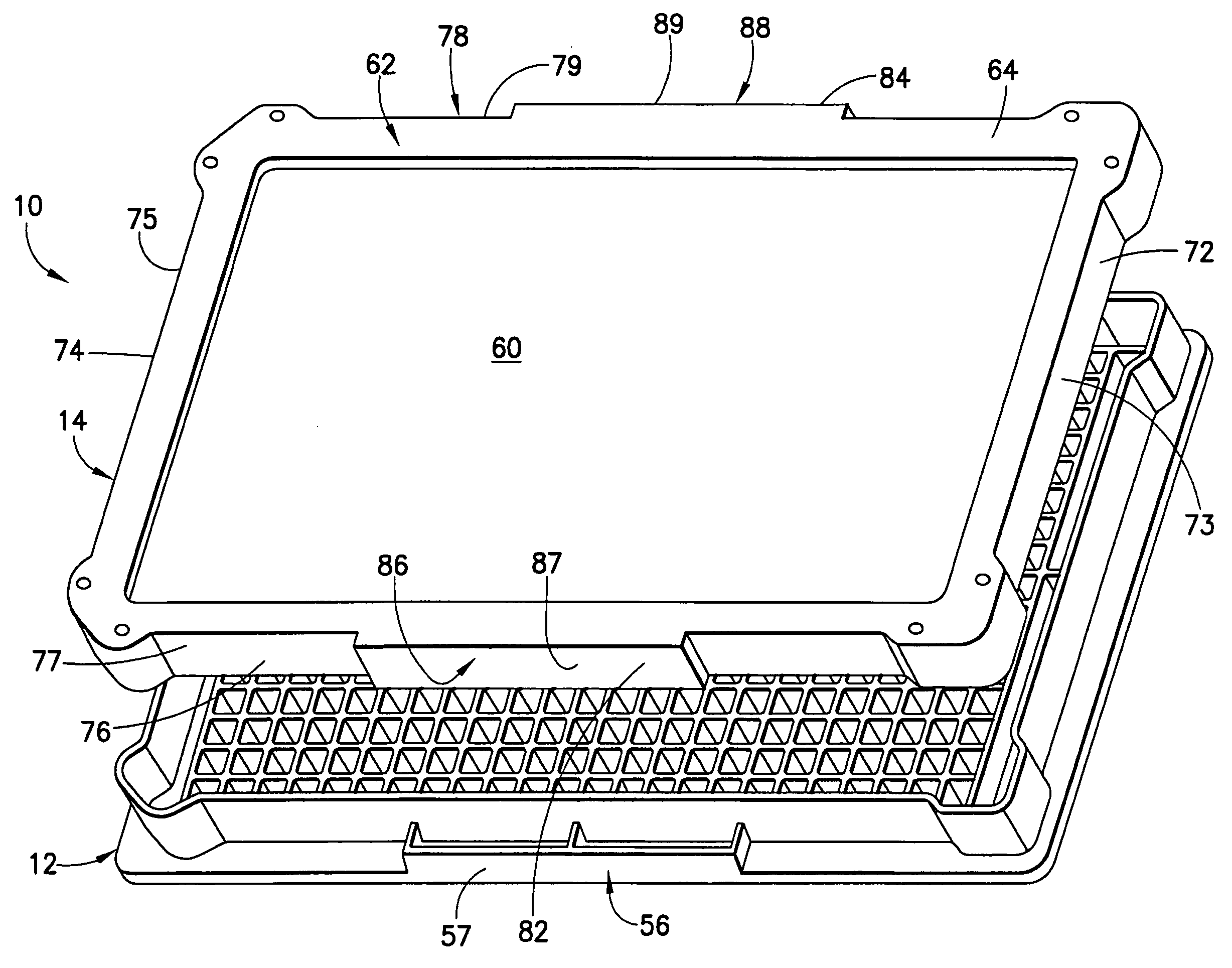
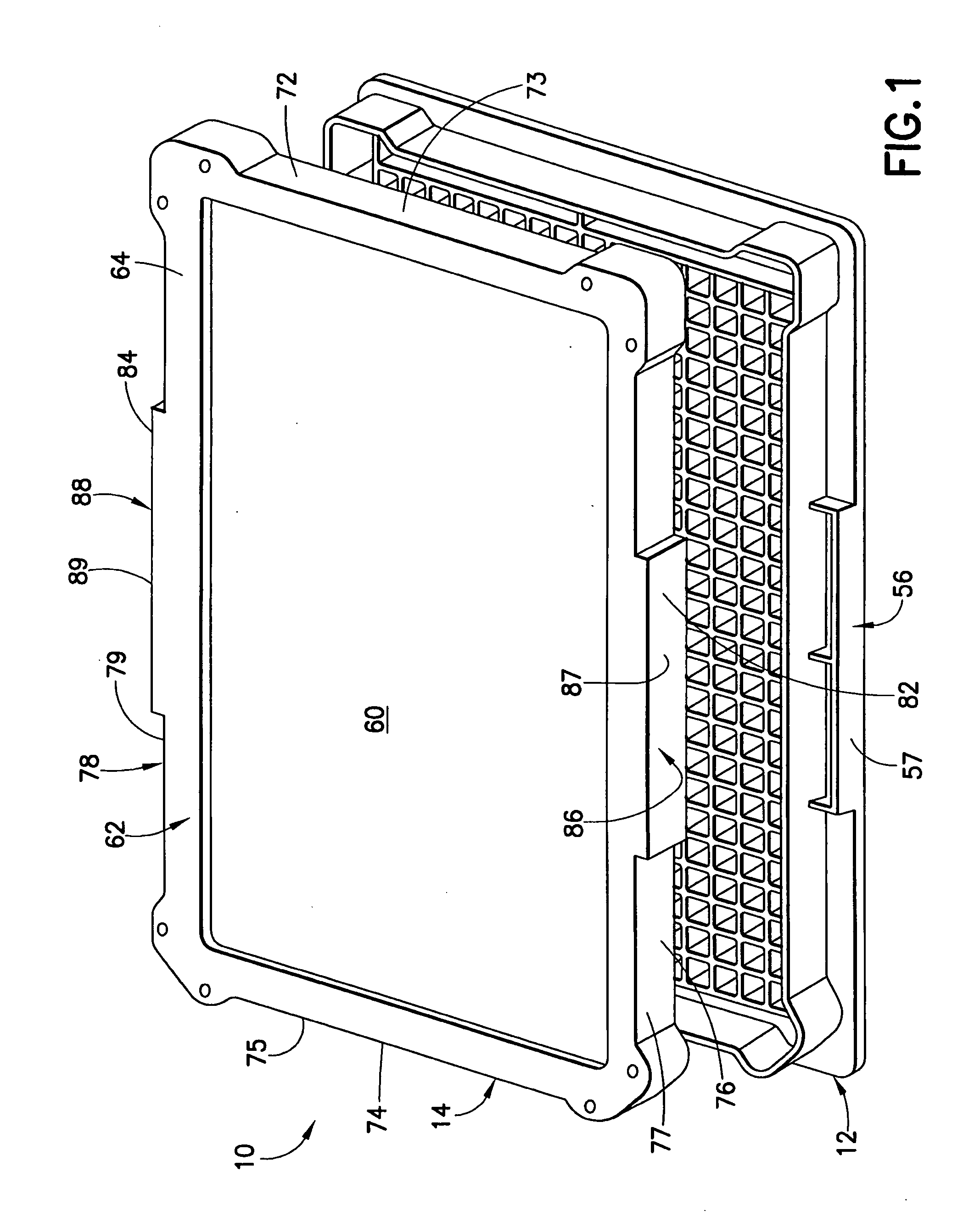
[0026] A plate assembly in accordance with the invention is identified generally by the numeral 10 in FIGS. 1 and 4-6. The plate assembly 10 includes a well plate 12 and a lid 14.

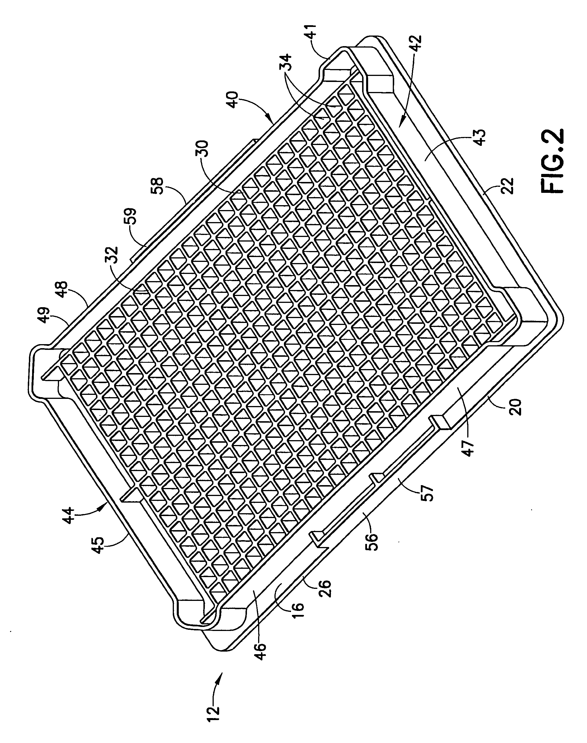
[0027] The well plate 12 is molded unitarily from a resin material such as polypropylene, polystyrene cyclic olfin, or polycarbonate. Well plate 12 includes a substantially planar base wall 16 and a downwardly depending skirt 20. Skirt 20 includes first and second substantially parallel ends 22 and 24 and first and second substantially parallel sides 26 and 28. Ends 22 and 24 are of substantially equal length and are substantially linear. Sides 26 and 28 also are of substantially equal length and are substantially linear. However, sides 26 and 28 are longer than ends 22 and 24. Thus, skirt 20 defines a substantially rectangular footprint for well plate 12. The dimensions of the footprint defined by skirt 20 of well plate 12 are selected in accordance with standardized dimensions for multi-wall plates and t...


PUM

PropertyMeasurementUnit
Distanceaaaaaaaaaa

Abstract

A well plate assembly includes a well plate with a base wall, a peripheral wall extending up from the base wall and spaced inwardly from the outer periphery of the base wall. A well array is formed on the base wall at locations inwardly from the peripheral wall. A lid is mounted on the peripheral wall of the well plate. The lid and the peripheral wall have areas that are indented from the outer periphery of the base wall to facilitate manipulation by robotic stacking equipment. The well plate and the lid further include substantially registered robotic gripper plates aligned with the outer periphery of the base wall to facilitate manipulation of the assembled well plate and lid by robotic grippers.

Description

RELATED APPLICATIONS [0001] This application claims the benefit of U.S. Provisional Application No. 60,557,977 filed on Mar. 31, 2004 which is hereby incorporated by reference in its entirety.BACKGROUND OF THE INVENTION [0002] 1. Field of the Invention [0003] The invention relates to an assembly of a micro-plate and a lid that can be manipulated by robotic stackers and / or by robotic arms. [0004] 2. Description of the Related Art [0005] Many laboratory procedures require analysis to be performed on chemicals or biological specimens, such as tissue cultured cells, proteins and enzymes. The specimen may be deposited in a liquid growth medium or buffer. An analysis then is performed after a specified time which will vary depending upon the nature of the biological specimen and the type of analysis that is to be performed. [0006] The chemical or biological specimen often is deposited in a micro-plate. The plate may be moved from a first location where the specimen is deposited to a secon...

Claims


Application Information

Patent Timeline
IPC IPC(8): B01L3/00B29C45/26G01N35/00G01N35/04
CPCB01L3/50853B01L2300/0829G01N35/028G01N35/0099G01N2035/00287B29C45/2673
Inventor SHANLER, MICHAEL S.
Owner CORNING INC
Why Eureka
Try Eureka