Guided power tool and method for operating a guided power tool

a power tool and guided technology, applied in the direction of portable power tools, manufacturing tools, portable drilling machines, etc., can solve problems such as machining problems, and achieve the effects of avoiding damage to the workpiece and/or an object embedded in it, improving operating comfort, and good work progress

Inactive Publication Date: 2005-10-20
ROBERT BOSCH GMBH
View PDF11 Cites 64 Cited by
  • Summary
  • Abstract
  • Description
  • Claims
  • Application Information

AI Technical Summary

Benefits of technology

[0005] The method according to the present invention enables, in a simple manner, the early detection of machining problems of this type, in particular the detection of objects embedded in the work piece, e.g., pipes or cables. Likewise, a change in the structure of the work piece can be detected as work progresses, and the power tool can adapt accordingly.
[0006] It is favorable to carry out detection and evaluation repeatedly during the work process. It is particularly favorable to carry out detection and evaluation permanently during the work process. The continual monitoring of suitable measured signals by an evaluation unit during the work process enables reliable detection of the inner condition of the work piece. The information obtained in this manner can be used to control or regulate the power tool in an optimal manner or to provide an operator with machining instructions or warning signals.
[0007] If the power tool automatically adapts to the property of the work piece, damage to the work piece and / or an object embedded in it, or the power tool itself, can be avoided. Furthermore, operating comfort can be improved while good work progress is made. If the intention is to drill through tiles attached to a wall, for example, the first step can be to start drilling gently, without percussion, using parameters suitable for tiles. If the evaluation unit then detects masonry or stone as the main structure, the power tool can then continue drilling using parameters that are suitable for the material involved, e.g., with the highest impact force and speed.

Problems solved by technology

The presence of embedded objects, openings and the like results in machining problems when an embedded object comes in contact with the insert tool or the insert tool breaks through into an opening.

Method used


Image

  • Guided power tool and method for operating a guided power tool
  • Guided power tool and method for operating a guided power tool

Examples


Embodiment Construction

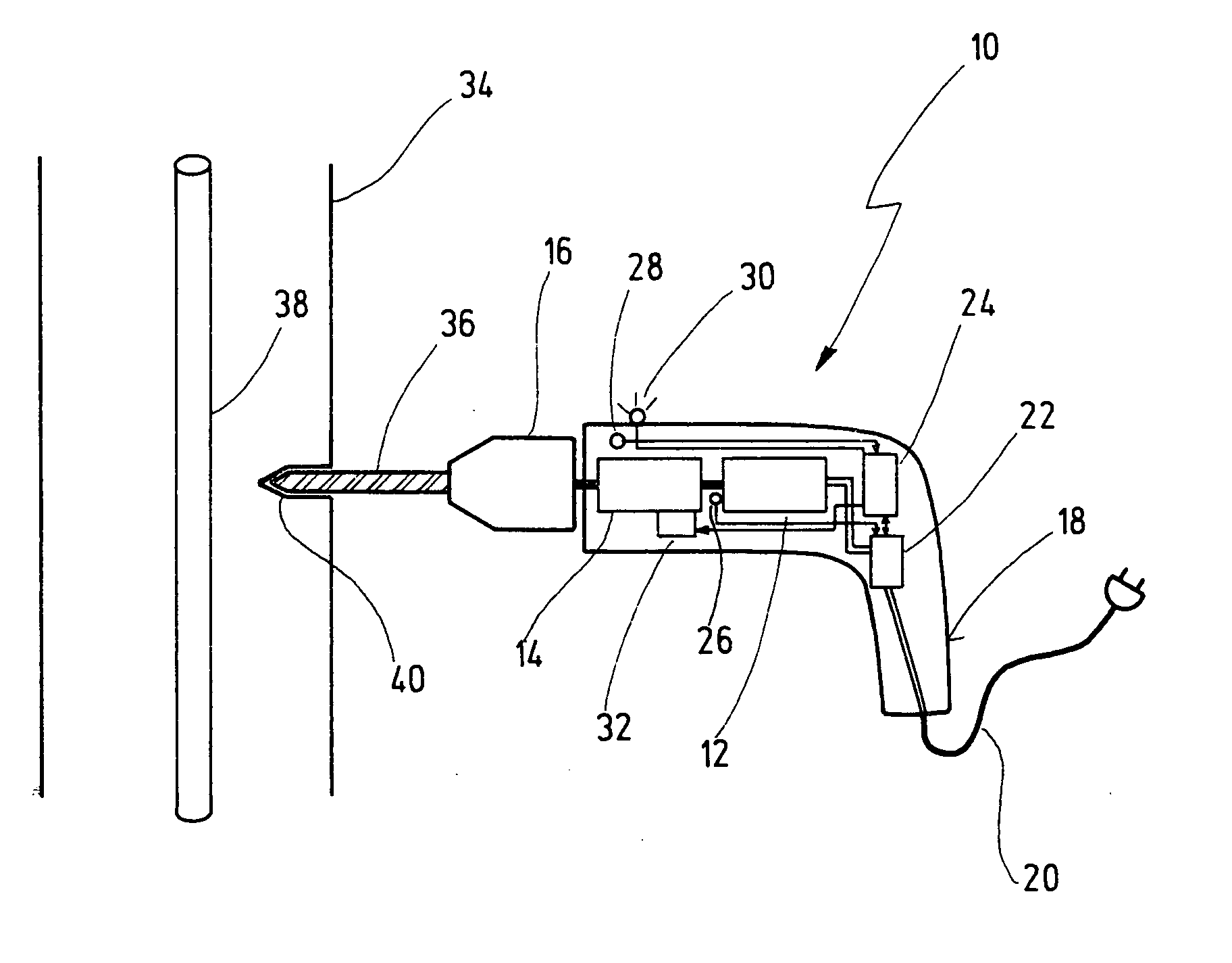
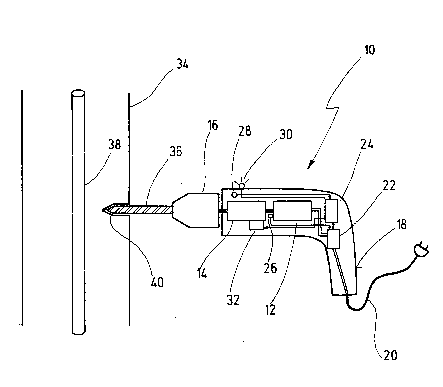
[0015] A preferred hand-guided power tool 10 is composed of a drive motor 12 located in a housing 18, the drive motor driving an insert tool 36 configured as a drill bit and retained in a detachable manner in a tool holder 16, and is further composed of a motor electronic unit 22 for controlling drive motor 12, and a striking mechanism 14. In the exemplary embodiment, striking mechanism 14 is equipped with a striking mechanism control 32, whereby striking mechanism 14 is drivable by drive motor 12, so that insert tool 36 can be driven in a percussive or rotating manner, with or without percussion. Separate drive units can also be provided for striking mechanism 14 and insert tool 36. Drive motor 12 is supplied with current via an electrical connecting cable 20. A rechargeable operating means can also be provided, as an option. A speed sensor 26 is provided on drive motor 12 to detect the rotational speed of drive motor 12.

[0016] With insert tool 36 configured as a drill, a hole 40 ...


PUM

PropertyMeasurementUnit
electrical voltageaaaaaaaaaa
rotational speedaaaaaaaaaa
torqueaaaaaaaaaa

Abstract

The present invention is based on a method for operating a guided power tool (10), in particular an electric power tool, with a rotatably and/or percussively driven insert tool (36), whereby the insert tool (36) is driven into a work piece (34) in a work process.
It is proposed that at least one measured signal detected at the power tool (10) during the work process is evaluated to derive a property of the work piece (34) located in the working direction of the insert tool (36), and the power tool (10) is operated in accordance with the property. A guided power tool is also proposed.

Description

BACKGROUND OF THE INVENTION [0001] The present invention is based on a guided power tool and a method for operating a guided power tool. [0002] Hand-guided power tools, in particular electric power tools, are used to drive an insert tool, e.g., a drill, in a work piece, e.g., a wall, whereby the insert tool can be driven in a percussive manner or a rotating manner with or without percussion. In this process, the power tools do not take into account material, structure-specific properties of the material, or foreign objects such as pipes or cables that can be embedded in the material. If a foreign object of this type is damaged by the insert tool, damage can result and the operator can even be endangered. [0003] Furthermore, position-finding devices are used-known examples are metal detection devices, “stud finders” and universal position-finding devices, for example-to locate objects such as electrical lines or pipes embedded in the wall. For an operator of a power tool it is comple...

Claims


Application Information

Patent Timeline
Patent Type & Authority Applications(United States)
IPC IPC(8): B21J1/00B23B45/16B23B45/02B23Q17/20B25D17/00B25F5/00
CPCB25F5/00B23B45/02B23Q17/20
Inventor STRASSER, ANDREASHOFFMANN, ERHARDHAHN, DIETMAR
Owner ROBERT BOSCH GMBH
Why Eureka
Try Eureka