Pressure release connection and pneumatic dispensing device

a technology of pressure release connection and pneumatic dispensing device, which is applied in the direction of liquid transfer device, separation process, instruments, etc., can solve the problems of increasing pressure inside the cartridge, affecting the sealing effect of the outlet, so as to reduce the compressive force and effectively seal the outlet

Inactive Publication Date: 2005-10-20
BLACK & DECKER INC
View PDF59 Cites 53 Cited by
  • Summary
  • Abstract
  • Description
  • Claims
  • Application Information

AI Technical Summary

Benefits of technology

[0004] In accordance with one aspect of the present invention, a pressure release connection for a pneumatic device adapted to be driven by a pressurized gas cartridge is provided. The pressure release connection includes a pressurized gas inlet adapted to receive pressurized gas from the pressurized gas cartridge. A variable compression member is adapted, under normal operating temperature conditions, to provide a norma...

Problems solved by technology

In cases where the temperature increases significantly, the pressure inside the cartridge might be ab...

Method used


Image

  • Pressure release connection and pneumatic dispensing device
  • Pressure release connection and pneumatic dispensing device
  • Pressure release connection and pneumatic dispensing device

Examples


Embodiment Construction

[0015] The following description of the preferred embodiment(s) is merely exemplary in nature and is in no way intended to limit the invention, its application, or uses. For example, although the device is described herein with respect to commonly available CO2 cartridges, alternative sources of high pressure gas may be used.

[0016] As used herein, “pressurized gas cartridge” means a container that is capable of housing a material that can be dispensed from the container in the form of a pressurized gas. Thus, it is possible that the material inside the container is, at least partially, in a form that is not gaseous. Similarly, the phrase “product cartridge” as used herein, means a container capable of housing a product for shipping and / or storage and for dispensing. Thus, the term “cartridge” does not, in itself, require any specific structural configuration.

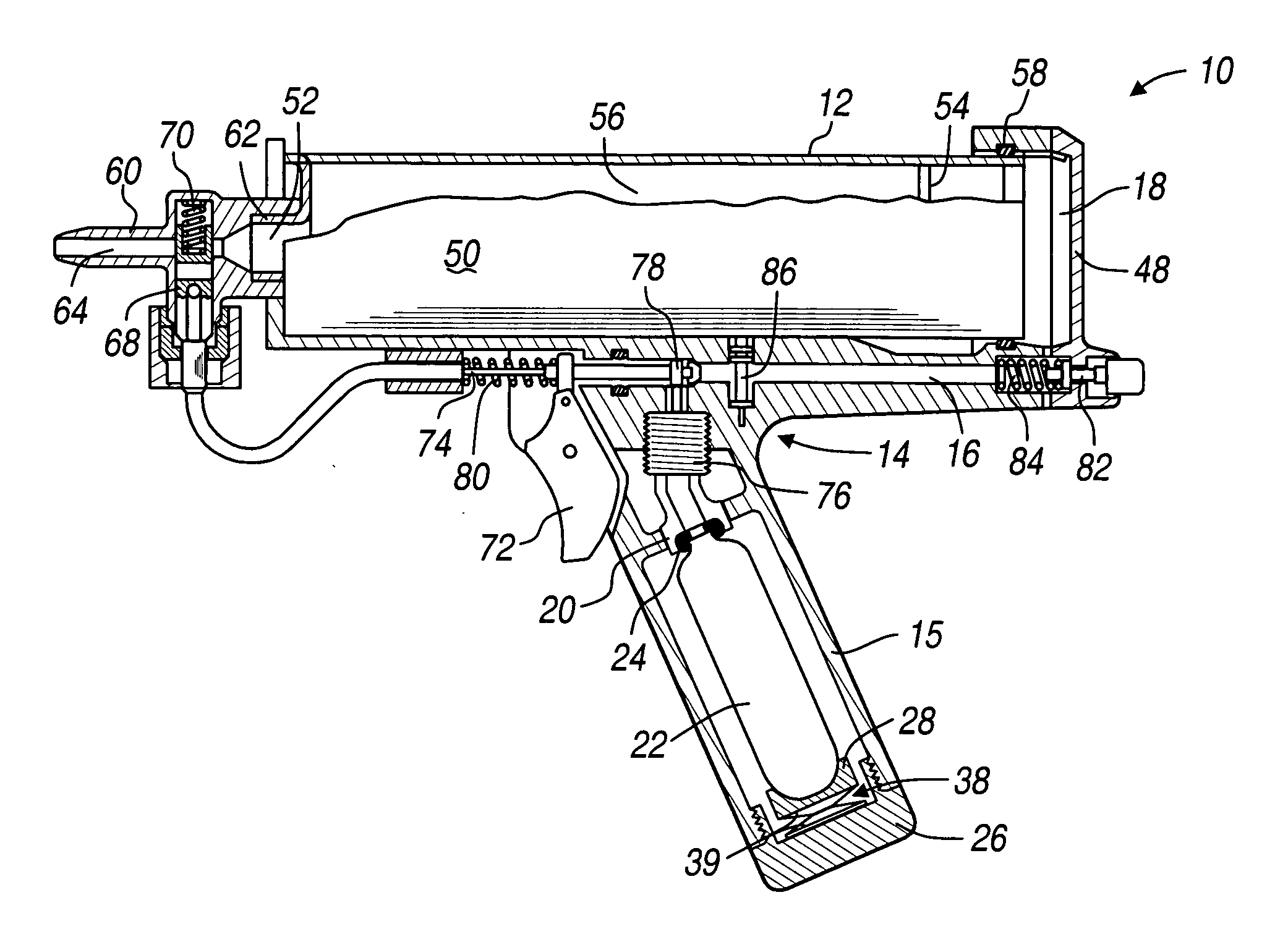
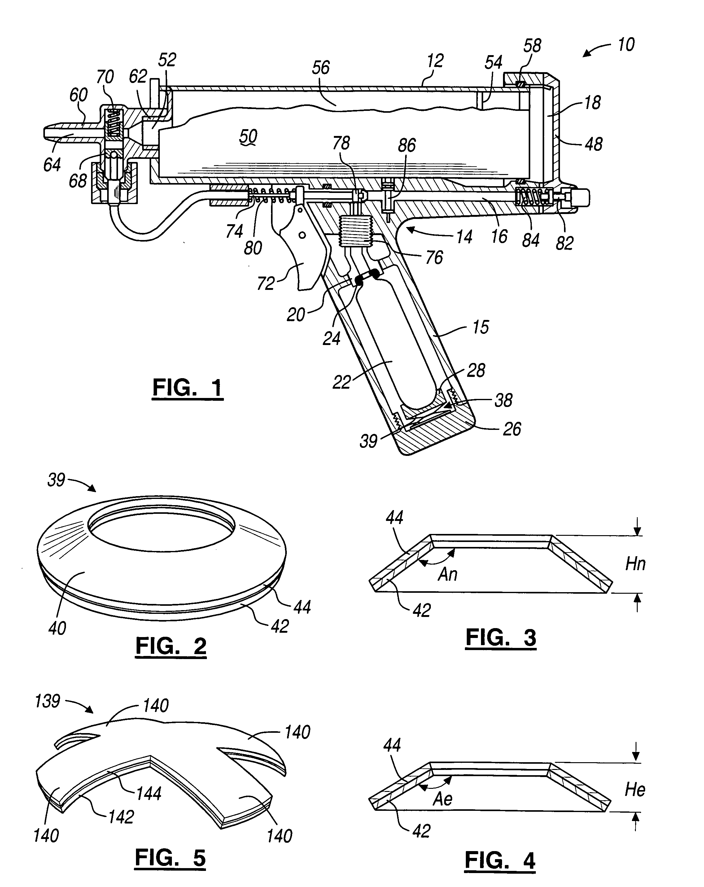
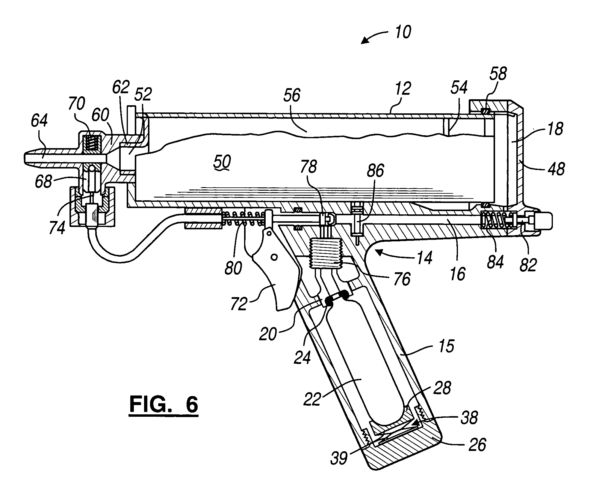
[0017] Referring to FIGS. 1 and 6, one preferred embodiment of a dispensing device 10 for dispensing a viscous product fro...


PUM

PropertyMeasurementUnit
Temperatureaaaaaaaaaa
Forceaaaaaaaaaa
Pressureaaaaaaaaaa

Abstract

An inlet is adapted to receive pressurized gas from a CO2 gas cartridge. A variable compression member has a normal height, under normal operating temperature conditions, adapted to provide a normal compressive force between the gas cartridge and the inlet to effectively seal the gas cartridge to the inlet. The variable compression member also has a reduced height, under heightened temperature conditions, adapted to provide a reduced compressive force between the gas cartridge and the inlet to allow pressurized gas to escape between the gas cartridge and the inlet. A seal member is compressed between the gas cartridge and the inlet. The inlet may be part of a pneumatic dispensing device. The gas inlet is in fluid communication with a gas enclosure to enable pressurized gas delivered through the inlet to provide a dispensing force on a product cartridge to cause dispensing of the viscous product.

Description

FIELD OF THE INVENTION [0001] The present invention relates to pressure release mechanisms; and more particularly, to such mechanisms for use with pressurized gas cartridges. BACKGROUND OF THE INVENTION [0002] Pressurized gas cartridges are sometimes used as a source of relatively high pressure gas. For example, commonly available CO2 cartridges have been used to provide pressurized gas to a dispensing device for viscous products. Exemplary viscous products include adhesives, caulks and sealants that are sold in product cartridges. The product cartridges typically have a cylindrical wall of cardboard or plastic and a movable piston. The piston is pushed by pneumatic pressure so that product is dispensed from the product cartridge through a dispensing orifice. Such dispensing devices are subject to use under a wide variety of environmental conditions. [0003] In devices that use pressurized gas cartridges as a source of relatively high pressure gas, the gas cartridge is sealed to an i...

Claims


Application Information

Patent Timeline
IPC IPC(8): B01D21/30B67D7/60B05C17/01B05C17/015
CPCB05C17/015B05C17/0146
Inventor CAMPBELL, DAVID C.
Owner BLACK & DECKER INC
Why Eureka
Try Eureka