Continuity tester with magnetic ground and method therefor

a continuity tester and magnetic ground technology, applied in short-circuit testing, instruments, air-break switches, etc., can solve the problems of inconvenient for users, and difficult to tell if the lamp unit is illuminated, so as to achieve effective grounding of the continuity tester

Inactive Publication Date: 2005-10-20
FLEMING DAVID R
View PDF3 Cites 0 Cited by
  • Summary
  • Abstract
  • Description
  • Claims
  • Application Information

AI Technical Summary

Benefits of technology

[0010] It is another object of the present invention to provide an improved continuity tester that has a way of signaling a user that continuity exists in a conductor when the continuity tester is used o...

Problems solved by technology

First, when using the continuity tester outdoors, it is difficult to tell if the lamp unit is illuminated.
This is due to the fact that sunlight shining on the lamp unit makes it difficult to tell if the lamp unit is illuminat...

Method used


Image

  • Continuity tester with magnetic ground and method therefor
  • Continuity tester with magnetic ground and method therefor
  • Continuity tester with magnetic ground and method therefor

Examples


Embodiment Construction

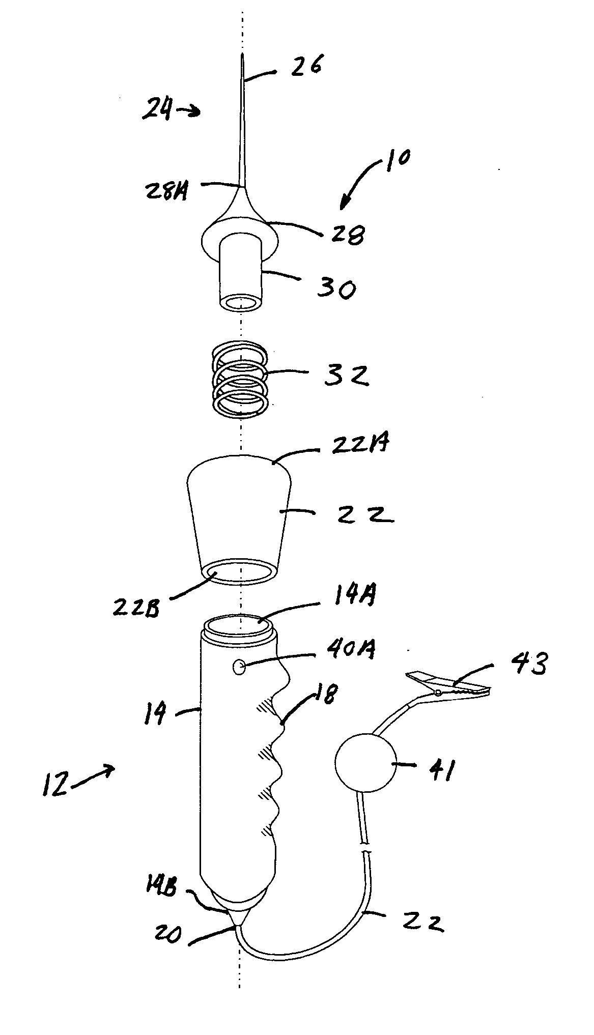
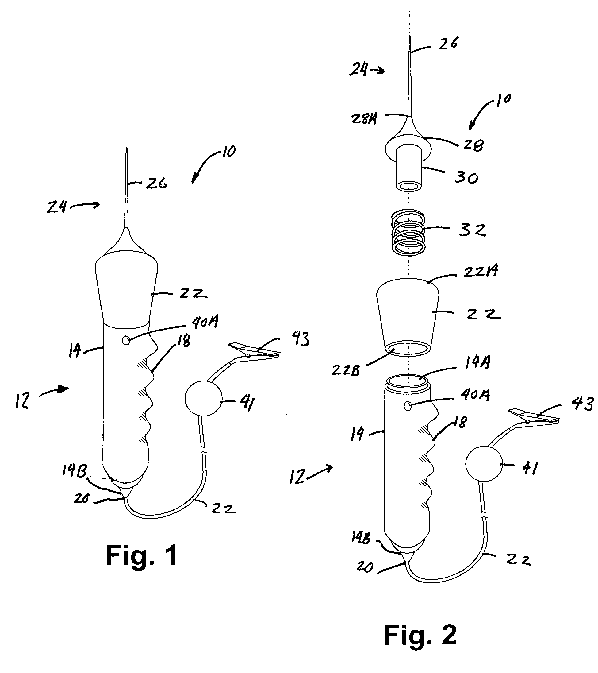
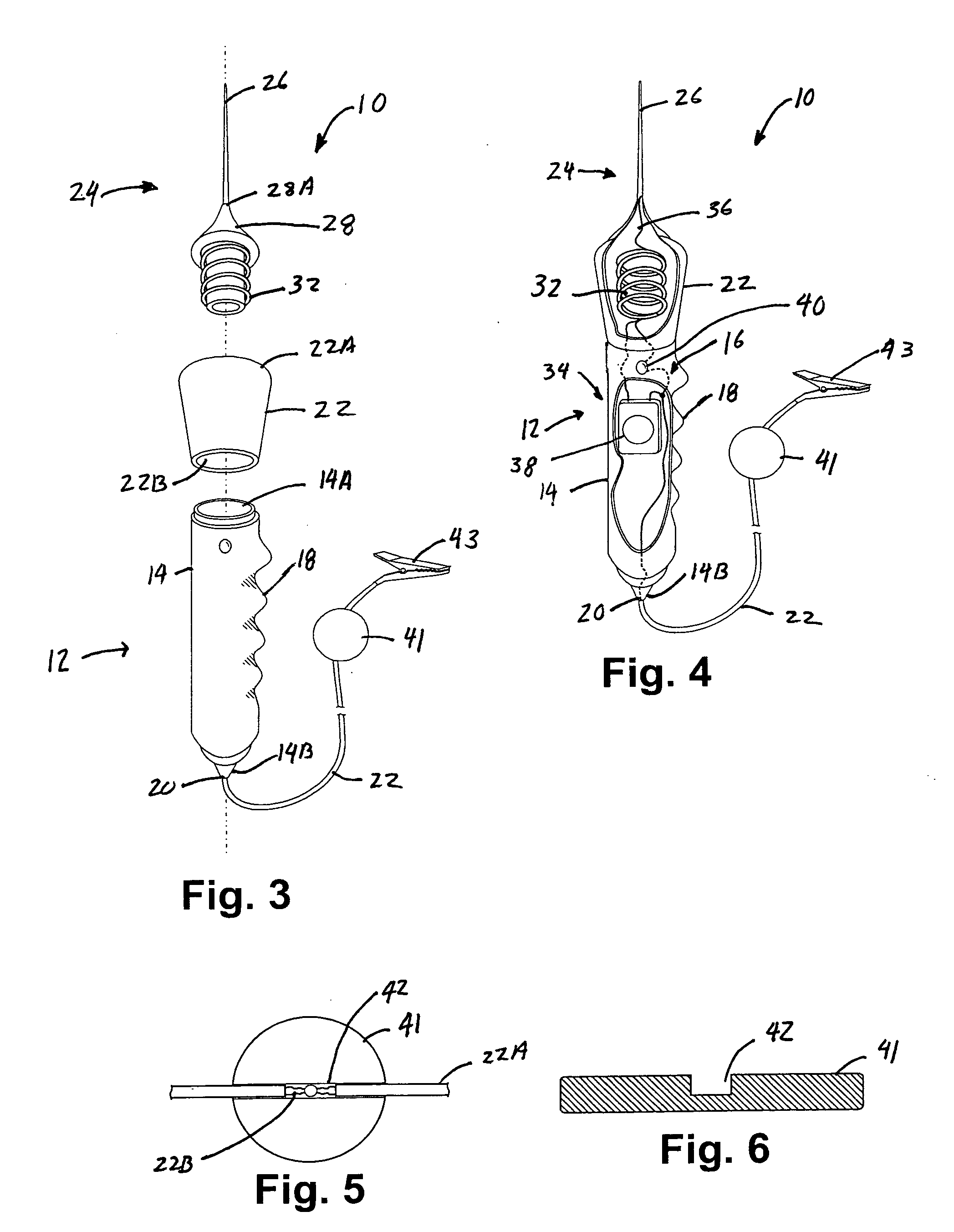
[0012] In accordance with one embodiment of the present invention a continuity testing device is disclosed. The continuity testing device has a probe element for contacting a conductor. A continuity testing circuit is coupled to the probe element. The continuity testing circuit has at least one of a vibrating or audible sensor to indicate electrical continuity of the conductor. A grounding wire is coupled to the continuity testing circuit. The grounding wire has a magnetic contact coupled thereto to ground the continuity testing device to any ferrous metallic grounded element. A housing is provided for holding and storing the probe element and the continuity testing circuit.

[0013] In accordance with one embodiment of the present invention a continuity testing device is disclosed. The continuity testing device has a probe element for contacting a conductor. A continuity testing circuit is coupled to the probe element. The continuity testing circuit has at least one of a vibrating or...


PUM


Abstract

A continuity testing device has a probe element for contacting a conductor. A continuity testing circuit is coupled to the probe element. The continuity testing circuit has at least one of a vibrating or audible sensor to indicate electrical continuity of the conductor. A grounding wire is coupled to the continuity testing circuit. The grounding wire has a magnetic contact coupled thereto to ground the continuity testing device to any ferrous metallic grounded element. A housing is provided for holding and storing the probe element and the continuity testing circuit.

Description

RELATED APPLICATIONS [0001] This patent application is claiming the benefit of U.S. Provisional Application entitled “CONTINUITY TESTER WITH MAGNETIC GROUND”, filed on Apr. 16, 2004, having a Ser. No. 60 / 562,951, and in the name of Fleming et al.BACKGROUND OF THE INVENTION [0002] 1. Field of the Invention [0003] This invention relates to testing equipment and, more specifically, to a continuity tester which uses a magnet for grounding the continuity tester and which further has two separate signaling devices for indicating electrical continuity of an electrical conductor. [0004] 2. Description of the Prior Art [0005] In general, a continuity tester is used to determine whether or not circuit continuity exists between probe points, an electrical conductor, etc. Most continuity testers have one or more probes. The probe is coupled in series with a source of potential. If continuity exists, a lamp unit in the continuity tester will illuminate indicating continuity is established. If no...

Claims


Application Information

Patent Timeline
IPC IPC(8): G01R31/02
CPCG01R31/026G01R31/52G01R31/54
Inventor FLEMING, DAVID R.
Owner FLEMING DAVID R
Why Eureka
Try Eureka