Image forming apparatus
- Summary
- Abstract
- Description
- Claims
- Application Information
AI Technical Summary
Benefits of technology
Problems solved by technology
Method used
Image
Examples
Example
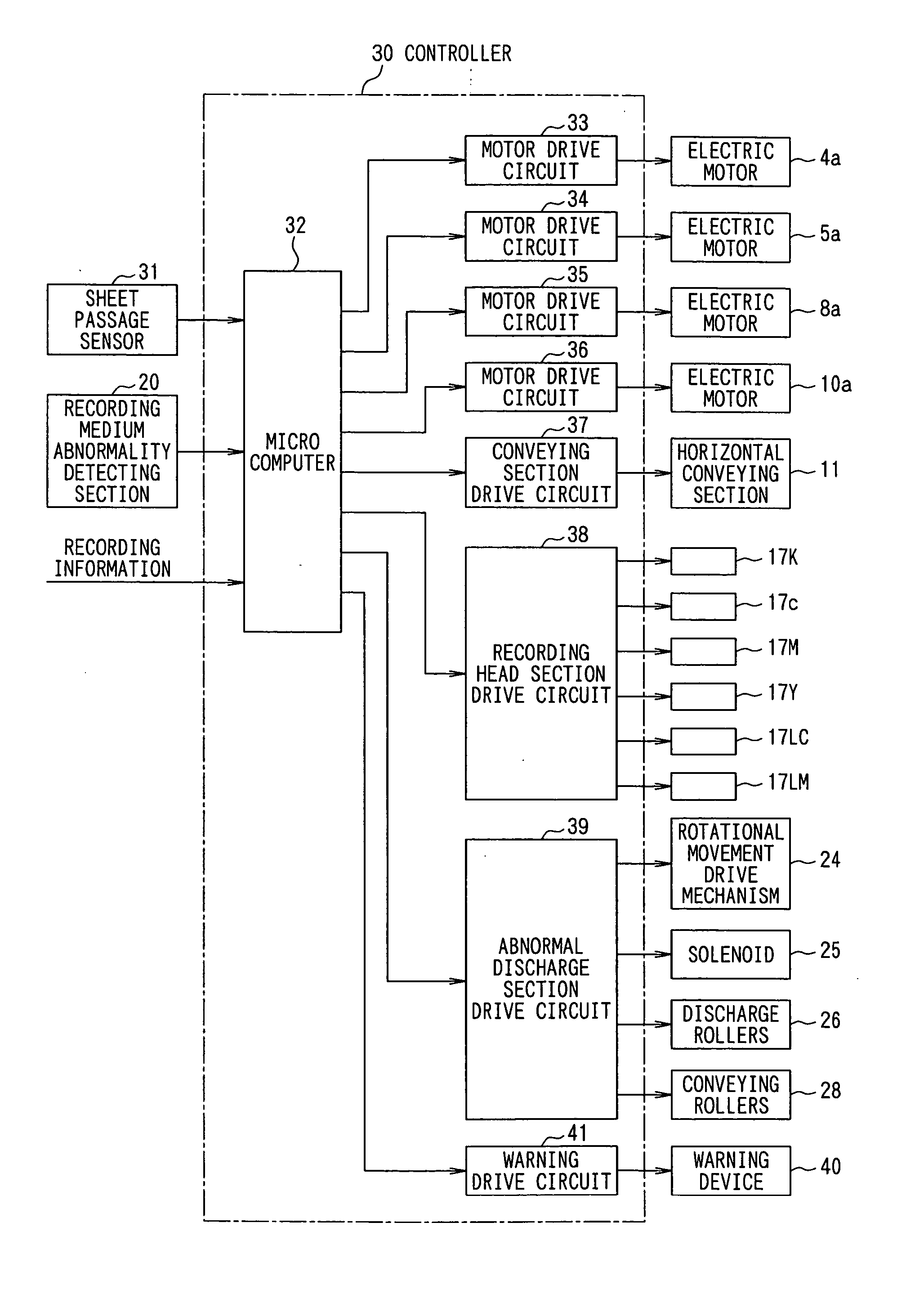
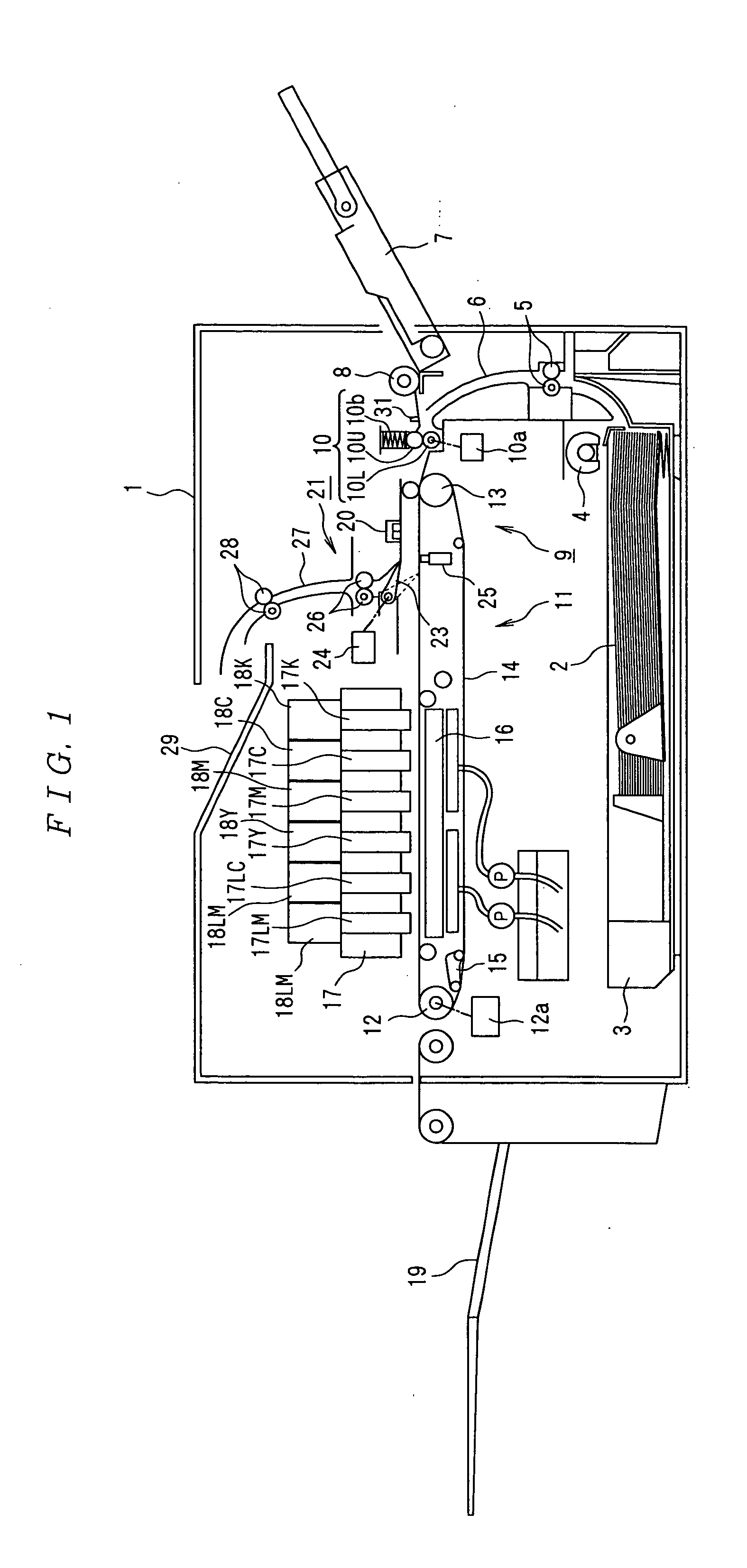
[0038]FIG. 1 is a schematic diagram showing a first embodiment of an image forming apparatus according to the invention. In the figure, reference numeral 1 denotes a box type case body. A sheet feeding cassette 3, which serves as a sheet feeding section housing a large number of recording sheets 2 serving as the recording media, is detachably mounted on a bottom of the inside of the case body 1. A sheet feeding roller 4, which feeds the recording sheets 2 one by one, is disposed on a sheet feeding side of the sheet feeding cassette 3. The recording sheet 2 fed by the sheet feeding roller 4 extends while curving upward and is guided by a conveying path 6 having a conveying roller 5 en route to convey to a center side of the case body 1 in a vertical direction.
[0039] A sheet feeding port for the recording sheet 2, which is fed from a sheet feeding roller 8 provided in a sheet feeding cassette for hand supply 7 serving as a sheet feeding section, is disposed at an upper end of the con...
Example
[0085] Next, an image forming apparatus according to a second embodiment of the invention will be explained with reference to FIGS. 10 to 13.
[0086] In the second embodiment, instead of providing the abnormal time conveying path as in the first embodiment, conveyance of the recording sheet 2 is stopped before reaching the recording head section 17 when abnormality of the recording sheet 2 is detected.
[0087] In the second embodiment, as shown in FIG. 10, the image forming apparatus has the same structure as the image forming apparatus according to the first embodiment shown in FIG. 1 except that the abnormal discharging section 21 is not provided. Components corresponding to those in FIG. 1 are denoted by the identical reference numerals and signs and detailed explanations of the components are omitted.
[0088] As shown in FIG. 11, the controller 30 has the same structure as that in the first embodiment shown in FIG. 3 except that the abnormal discharging section drive circuit 39 is ...
Example
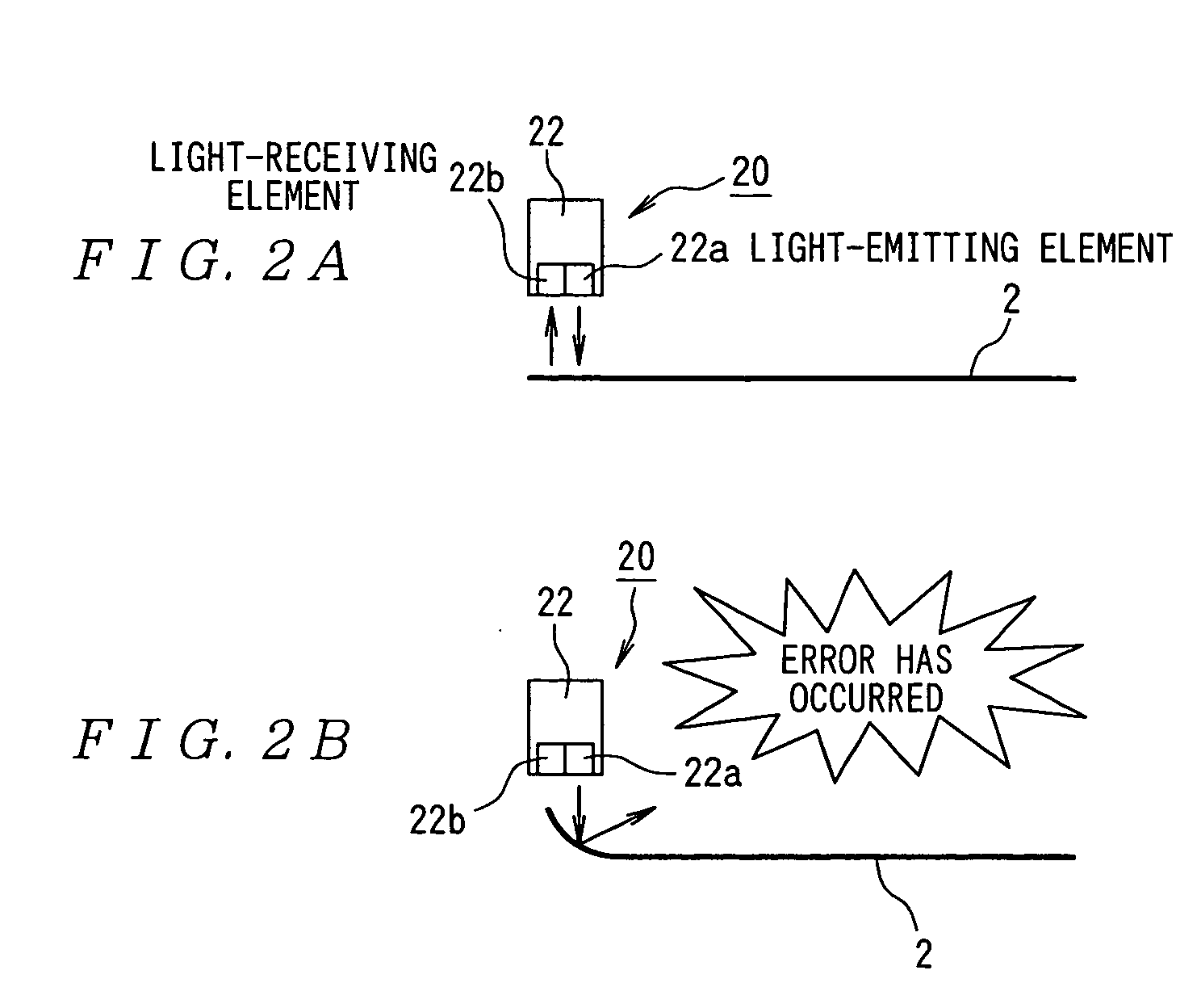
[0115] In the explanations of the first and the second embodiments, the reflection-type optical sensor, in which the light-emitting element 22a and the light-receiving element 22b are set in close contact with each other, is applied as the recording medium abnormality detecting section 20. However, the invention is not limited to this. As shown in FIGS. 14A and 14B, the light-emitting element 22a is arranged to be slanted, for example, 45 degrees and light reflected from the conveyor belt 13 or the recording sheet 2 is made incident on the light-receiving element 22b slanted 45 degrees. When abnormality due to lift does not occur at the leading edge of the recording sheet 2, as shown in FIG. 14A, light emitted from the light-emitting element 22 is reflected on the conveyor belt 13 or the recording sheet 2, and the reflected light is made incident on the light-receiving element 22b, and a signal with a logical value “1” is outputted from the light-receiving element 22b. When abnormal...
PUM
 Abstract
Description
Claims
Application Information
 - R&D
- Intellectual Property
- Life Sciences
- Materials
- Tech Scout
- Unparalleled Data Quality
- Higher Quality Content
- 60% Fewer Hallucinations
Browse by: Latest US Patents, China's latest patents, Technical Efficacy Thesaurus, Application Domain, Technology Topic, Popular Technical Reports.
© 2025 PatSnap. All rights reserved.Legal|Privacy policy|Modern Slavery Act Transparency Statement|Sitemap|About US| Contact US: help@patsnap.com


