Display device and controller
- Summary
- Abstract
- Description
- Claims
- Application Information
AI Technical Summary
Benefits of technology
Problems solved by technology
Method used
Image
Examples
first embodiment
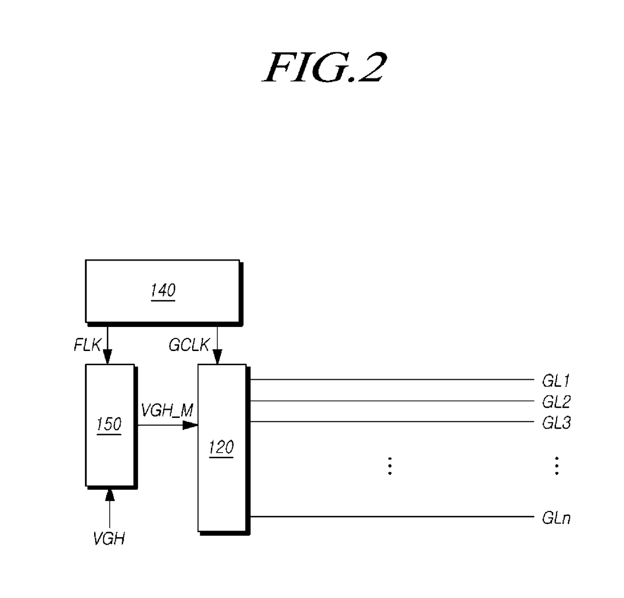
[0050]FIGS. 5 and 6 are diagrams illustrating a configuration of adjusting an output of a gate pulse modulation integrated circuit in a display device according to a
[0051]FIG. 5 illustrates a configuration of the display device 100 according to a first embodiment, and illustrates an example of adjusting a waveform of a signal output by the gate pulse modulation integrated circuit 150. With reference to FIG. 5, the display device 100 according to the first embodiment may include the plurality of gate lines GL arranged in the display panel 110, the gate driver 120 that may output scan signals to the gate lines GL, the gate pulse modulation integrated circuit 150 that may output a modulated gate high voltage VGH_M, and the controller 140 that may output a gate pulse modulation signal FLK and a gate clock signal GCLK and may control driving of the gate driver 120.
[0052]The controller 140 may output the gate pulse modulation signal FLK to the gate pulse modulation integrated circuit 150,...
second embodiment
[0068]FIG. 8 is a diagram illustrating a display panel and a gate pulse modulation integrated circuit in a display device according to a
[0069]FIG. 8 illustrates the gate pulse modulation integrated circuit 150 and the gate lines GL arranged in the display panel 110 in the display device 100 according to the second embodiment. With reference to FIG. 8, the display panel 110 in the display device 100 according to the second embodiment may have the plurality of gate lines GL sequentially arranged therein, and may include one or more dummy lines (Dummy Lines) arranged in parallel with the gate lines GL.
[0070]In the display panel 110, the plurality of gate lines GL may be arranged in a display area (A / A) in which an image is displayed, and the dummy lines may be arranged in a non-display area (N / A) in which no image is displayed. The dummy lines may be arranged subsequent to a gate line GL to which a last scan signal of scan signals sequentially output is applied.
[0071]Further, the scan ...
PUM
 Abstract
Description
Claims
Application Information
 - R&D
- Intellectual Property
- Life Sciences
- Materials
- Tech Scout
- Unparalleled Data Quality
- Higher Quality Content
- 60% Fewer Hallucinations
Browse by: Latest US Patents, China's latest patents, Technical Efficacy Thesaurus, Application Domain, Technology Topic, Popular Technical Reports.
© 2025 PatSnap. All rights reserved.Legal|Privacy policy|Modern Slavery Act Transparency Statement|Sitemap|About US| Contact US: help@patsnap.com


