
Versatile system for signal shaping in ultra-wideband communications

Inactive Publication Date: 2005-10-20
TEXAS INSTR INC
View PDF6 Cites 26 Cited by
  • Summary
  • Abstract
  • Description
  • Claims
  • Application Information

AI Technical Summary

Benefits of technology

[0011] The present invention provides a versatile system, comprising various structures and methods, for maximizing utilization and efficiency of ultra-wideband communications through pre-transmission signal shaping. The system of the present invention provides pre-equalization of UWB transmission signals. By the present invention, signals can be compensated, on a fixed or dynamic basis, to optimize transmission power across a signal spectrum. The system of the present invention also provides for selective alteration, again on a fixed or dynamic basis, of a transmission signal spectrum—providing wireless devices that may be adapted to varying, location-dependent regulatory requirements. The present invention is readily adaptable to a number of design requirements and variables—and may be implemented utilizing hardware already present in conventional wireless devices. The present invention thus provides efficient and reliable UWB data transmission in an easy, cost-effective manner.
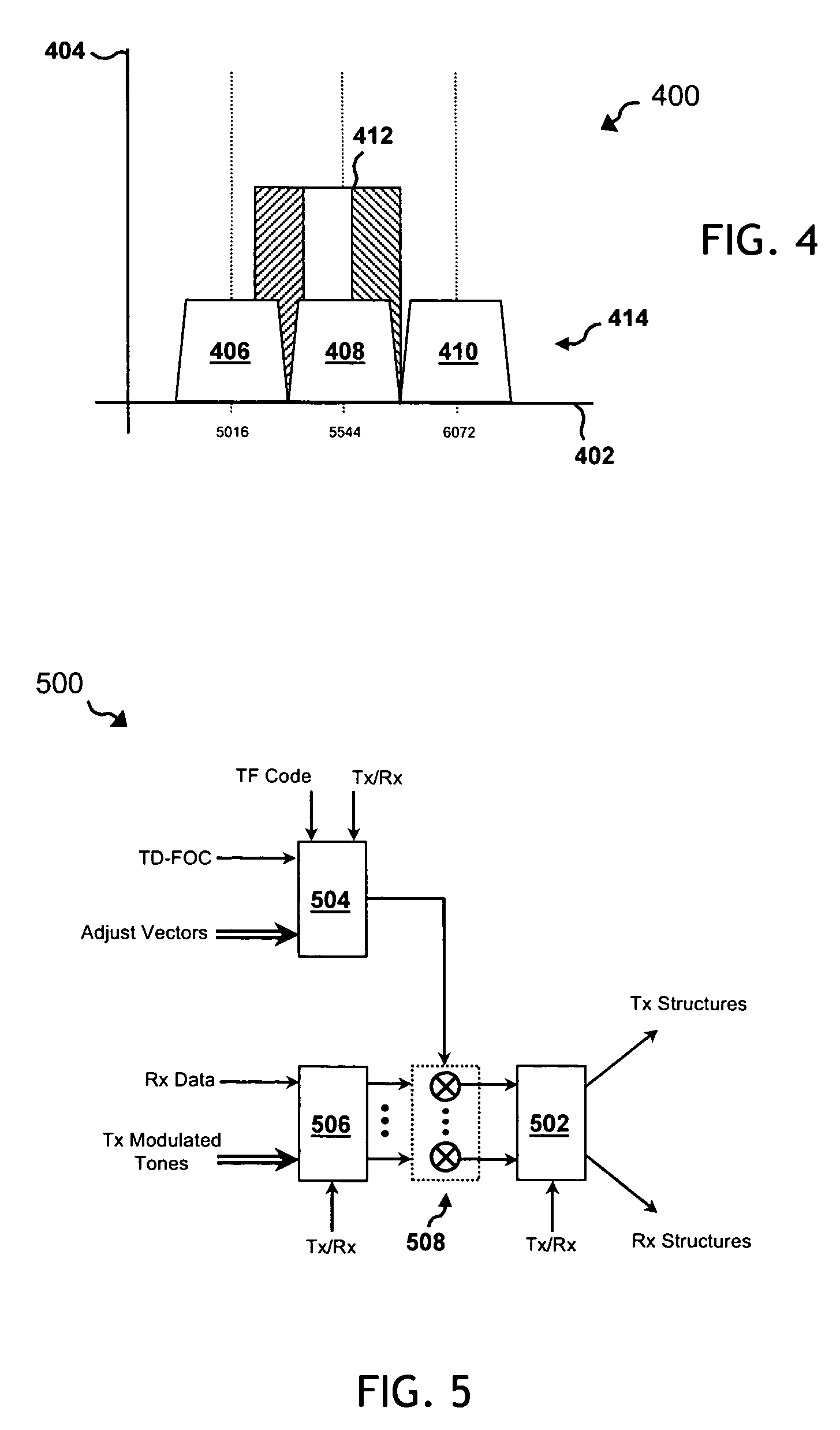
[0012] Specifically, the present invention provides structures and methods that perform a digital pre-equalization of a UWB transmission signal spectrum. The present invention provides selective augmentation and reduction at multiple instances across the spectrum, utilizing existing device hardware. The present invention provides digital pre-equalization that compensates frequency shaping commonly introduced by transmission components (e.g., front-end filters, antenna equipment). The present invention provides control of a DC term at an IFFT input, enabling suppression of carrier leak-through. The present invention further provides spectral shaping of UWB emissions to either avoid certain victim receiver bands, or to limit emissions in these bands. The present invention recognizes and exploits the half duplex nature of UWB communications, to provide its benefits in an efficient architecture—one that utilizes circuitry commonly available in the receiver portion of many UWB transceiver devices.

Problems solved by technology

Since wireless communications rely on over-the-air (OTA) transmissions, wireless systems and their operation are subjected to a number of regulatory requirements and restrictions.
These regulatory influences can vary considerably, and even conflict, across different countries or regions.
This UWB frequency allocation is unlicensed, leaving the spectrum open to a number of potentially conflicting technologies.
Due to this unlicensed nature, UWB devices and systems have to contend with both pre-existing and future-developed services that share some portion of that frequency range.
Furthermore, compliance with global regulatory standards may require conformance to, for example, regionally dependent spectral limitations.
Moreover, the relative strength (i.e., power) of UWB signals is also limited to a transmit power of −41.25 dBm / MHz.
Due to this relatively low-power, short-range nature of UWB, even a nominal degree of signal fading or interference could significantly impact signal integrity or transmission efficiency.
As a practical matter, though, signal processing that is inherent in transmitter / receiver hardware (e.g., analog filter circuitry, antenna hardware) generally causes some degree of loss and results in non-optimal transmission power, especially along the outer ranges of the signal spectrum.

Method used


Image

  • Versatile system for signal shaping in ultra-wideband communications
  • Versatile system for signal shaping in ultra-wideband communications
  • Versatile system for signal shaping in ultra-wideband communications

Examples


Embodiment Construction

[0021] While the making and using of various embodiments of the present invention are discussed in detail below, it should be appreciated that the present invention provides many applicable inventive concepts, which can be embodied in a wide variety of specific contexts. The present invention is hereafter illustratively described primarily in conjunction with the design and operation of an ultra-wideband (UWB) communications system. Certain aspects of the present invention are further detailed in relation to design and operation of multi-band Orthogonal Frequency Division Multiplexing (OFDM) communications system. Although described in relation to such structures, the teachings and embodiments of the present invention may be beneficially implemented with a variety of data transmission or communication systems or protocols (e.g., IEEE 802.11), depending upon the specific needs or requirements of such systems. The specific embodiments discussed herein are, therefore, merely demonstrat...


PUM


Abstract

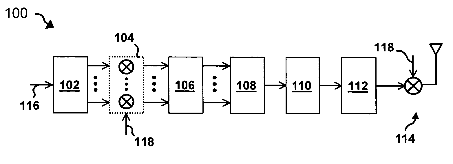
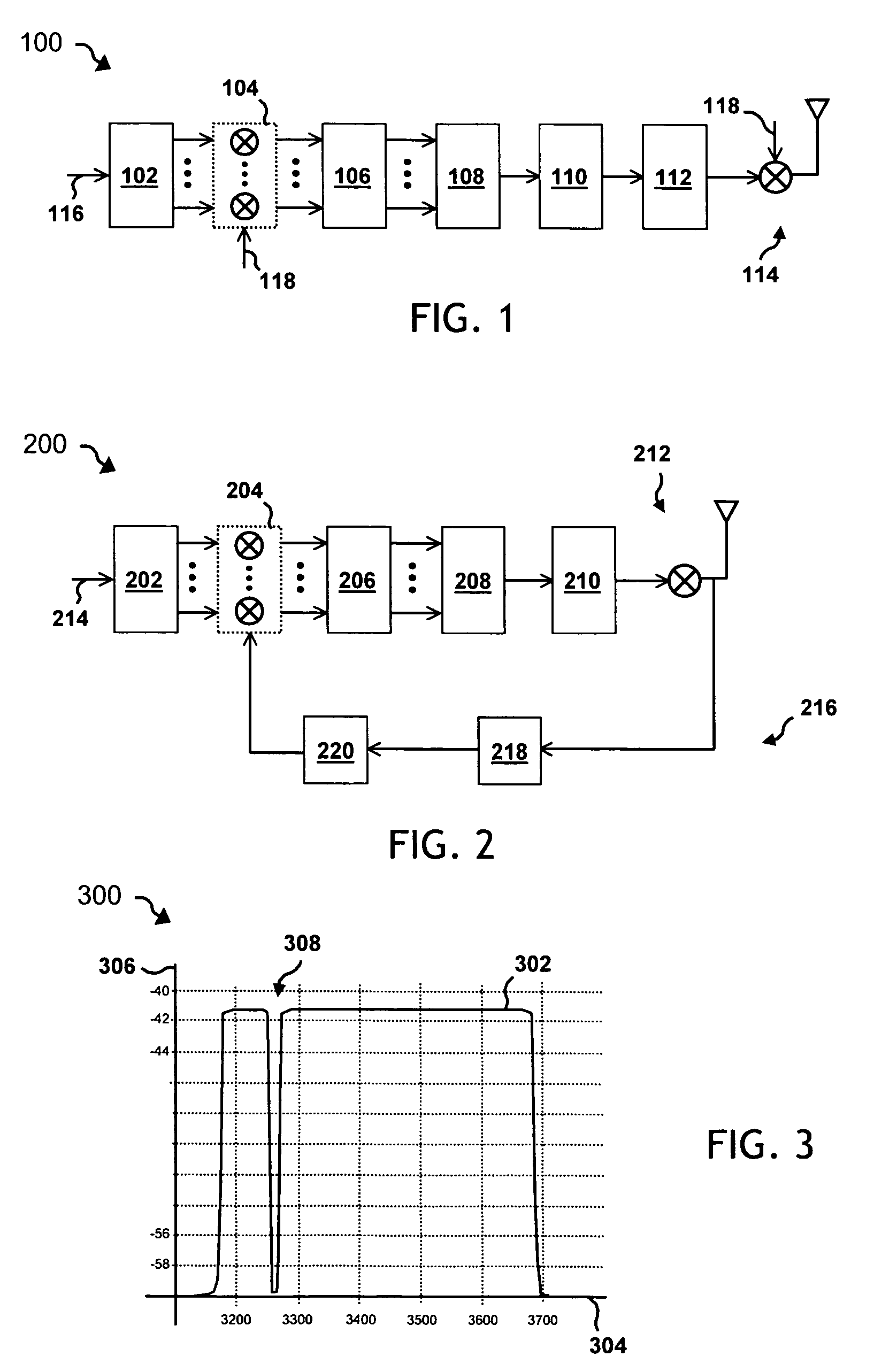
The present invention provides a versatile system for selectively altering or shaping transmission signals in an ultra-wideband communications system (100). The system provides a serial to parallel conversion function (102) with a serial data input (116). The serial to parallel conversion function converts the serial data and outputs it in parallel format. An adjustment function (104) receives the now parallel data and selectively alters the parallel data responsive to some code or vector (118). A frequency-to-time-domain conversion function (106) receives the selectively altered parallel data and transmits it to a parallel-to-serial conversion function 108. The now serial data transfer through an OFDM prefix / suffix function 110 and a digital-to-analog conversion function 112, to an up conversion mixer function 114. Encoded digital data bits are input, converted to parallel format, and passed to the spectrum adjustment function, which provides selective adjustment of specific data units (i.e., specific OFDM sub-carriers or tones).

Description

PRIORITY CLAIM [0001] This application claims priority of U.S. Provisional Application No. 60 / 564,327, filed Apr. 20, 2004.TECHNICAL FIELD OF THE INVENTION [0002] The present invention relates generally to the field of wireless communications and, more particularly, to structures and methods for maximizing utilization and efficiency of ultra-wideband communications through pre-transmission signal shaping. BACKGROUND OF THE INVENTION [0003] Increasing demand for more powerful and convenient data and information communication has spawned a number of advancements in communications technologies, particularly in wireless communication technologies. A number of technologies have been developed to provide the convenience of wireless communication in a variety of applications, in various locations. This proliferation of wireless communication has given rise to a number of manufacturing and operational considerations. [0004] Since wireless communications rely on over-the-air (OTA) transmissi...

Claims


Application Information

Patent Timeline
IPC IPC(8): H04B1/69H04L25/03
CPCH04B1/71632H04L2025/03414H04L25/03343H04B1/719
Inventor BALAKRISHNAN, JAIGANESHLINGAM, SRINIVASBATRA, ANUJ
Owner TEXAS INSTR INC
Learn More