Line state detecting apparatus and transmitting apparatus and receiving apparatus of balanced transmission system

Inactive Publication Date: 2005-10-20
PANASONIC CORP
View PDF8 Cites 174 Cited by
  • Summary
  • Abstract
  • Description
  • Claims
  • Application Information

AI Technical Summary

Benefits of technology

[0008] Further, it is an object of the invention to provide a transmitting apparatus and a receiving apparatus of a balanced transmission system capable of co

Problems solved by technology

Thereby, an unbalance state of an unbalance component of cur

Method used


Image

  • Line state detecting apparatus and transmitting apparatus and receiving apparatus of balanced transmission system
  • Line state detecting apparatus and transmitting apparatus and receiving apparatus of balanced transmission system
  • Line state detecting apparatus and transmitting apparatus and receiving apparatus of balanced transmission system

Examples


first embodiment

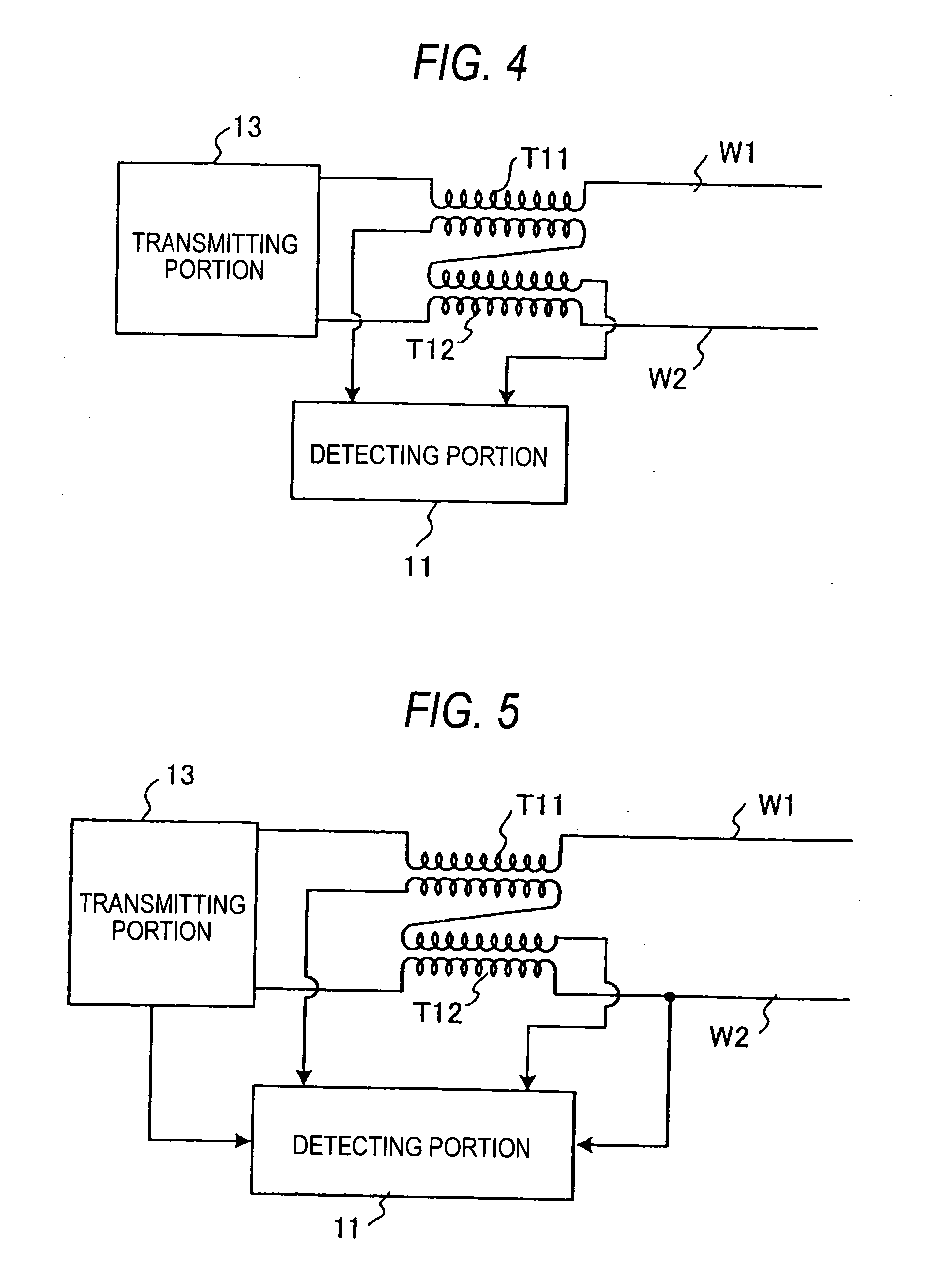
[0071]FIG. 4 is a view showing a basic constitution of a line state detecting apparatus according to a first embodiment of the invention. The line state detecting apparatus of the embodiment includes current transformers T11, T112 primary sides (primary windings) of which are respectively inserted to transmission lines of a forward line side and a rearward line side comprising a pair of conductors W1, W2 connected to the transmitting portion 13 in series therewith. Secondary sides (secondary windings) of the current transformers T21, T22 are connected in series to respectively cancel currents or voltages in the two transformers. Further, the line state detecting apparatus is constructed by a constitution of including the detecting portion 11 for detecting currents or voltages on secondary sides of the current transformers T11, T12.

[0072] In the constitution, the detecting portion 11 can directly detect a common mode current (unbalance current) constituting a difference of the curre...

second embodiment

[0079]FIG. 8 is a view showing a basic constitution of a line state detecting apparatus according to a second embodiment of the invention. According to the line state detecting apparatus of the embodiment, in the transmission lines of the forward line side and the rearward line side comprising the pair of conductors W1, W2 connected to the transmitting portion 23, a first and a second winding are inserted respectively to the conductors W1, W2 in series therewith and a common mode coil L21 having a third winding for detecting a common mode is provided. Further, the line state detecting apparatus is constructed by a constitution of including a detecting portion 21 for detecting a common mode current or an unbalance voltage between the conductors W1, W2 induced at the third winding by detecting a voltage or a current across both ends of the third winding of the common mode coil L21.

[0080] In the constitution, the detecting portion 21 can directly detect a common mode current (unbalanc...

third embodiment

[0090]FIG. 13 is a view showing a basic constitution of a line state detecting apparatus according to a third embodiment of the invention. The line state detecting apparatus of the embodiment is constituted by including, in transmission lines comprising the pair of conductors W1, W2 connected to a transmitting portion 33, a transformer T31 for transmission having a middle point tap on a secondary side of a side of the transmission lines inserted between the transmission lines and the transmitting portion 33, an impedance Z31 inserted between the middle point tap on the secondary side of the transmission transformer T31, and a detecting portion 31 for detecting a voltage across both ends of the impedance Z31.

[0091] In the constitution, the detecting portion 31 can directly detect a common mode voltage (unbalance voltage) of the conductors W1, W2 of the transmission lines by a voltage between the middle point on the secondary side of the transmission transformer T31 and a ground pote...


PUM


Abstract

A line state detecting apparatus provided in a balanced transmission system includes, in transmission lines comprising a pair of conductors W1, W2 connected to a transmitting portion 13, current transformers T11, T12 primary sides of which are inserted to respectives thereof in series therewith and secondary sides of which are connected in series to cancel currents or voltages of the two transformer by each other, and a detecting portion 11 for detecting currents or voltages on secondary sides of the current transformers T11, T12. By an output of the detecting portion 11, a difference of currents or voltages of the conductors W1, W2 of the transmission lines is provided and an unbalance component between the conductors W1, W2 is detected.

Description

BACKGROUND OF THE INVENTION [0001] The present invention relates to a line state detecting apparatus for detecting a state of a transmission line in a balanced transmission system for transmitting data by using a pair of conductors, and a transmitting apparatus and a receiving apparatus of a balanced transmission system provided therewith. [0002] In a background art, there is widely used a balanced transmission system for transmitting data by using a pair of transmission lines brought into a balanced state. In a balanced transmission system of this kind, as in, for example, a telephone line, a transmission line by an exclusive communication line or the like is frequently used, normally, some degree of balance is moderately maintained by current flowing via a forward line or a rearward line of pair of transmission line. [0003]FIG. 31 shows an example of a transmitting portion and a transmission line of a balanced transmission apparatus of a background art. The balanced transmission a...

Claims


Application Information

Patent Timeline
IPC IPC(8): H04B3/30H04B3/56
CPCH04B3/30H04B3/56H04B2203/5491H04B2203/5445H04B2203/5483H04B2203/5425
Inventor ICHIHARA, FUMIOYAMASHITA, AKIHIROHANADA, TSUNEHIROOISHI, MUTSUHIKOWAKISAKA, TOSHIYUKIMAKI, MASAHIRO
Owner PANASONIC CORP
Why Eureka
Try Eureka