Balanced hydrogen feed for a fuel cell

a fuel cell and hydrogen feed technology, applied in the field of fuel cells, can solve the problems of uniform channel lengths and unintended reactant distribution of anodes, and achieve the effect of facilitating flow balancing and facilitating flow balancing

Active Publication Date: 2007-08-30
GM GLOBAL TECH OPERATIONS LLC
View PDF11 Cites 23 Cited by
  • Summary
  • Abstract
  • Description
  • Claims
  • Application Information

AI Technical Summary

Benefits of technology

[0012] In one embodiment, the plate comprises a plate having a flow field formed therein, the flow field defined by a plurality of channels formed on an outer surface thereof, the channels of the flow field adapted to provide communication between a source of gas and an exhaust header; and an active region of the flow field including at least a portion of the channels, the active region including a diffusion medium adjacent thereto, at least a portion of the gas consumed in the active region to cause a difference in volumetric flow of the gas upstream of the active region and downstream of the active region, wherein at least a portion of the channels includes a branched section forming a plurality of branched channels to facilitate a balancing of a flow of the gas therethrough.
[0013] In another embodiment, the plate comprises a plate having a first side and a second side; and a flow field formed in a first side of the plate, the flow field further comprising an inlet feed region; an outlet feed region; a plurality of inlet flow channels formed in the inlet feed region on an outer surface of the plate in communication with a source of gas; a plurality of outlet flow channels formed in the outlet feed region on an outer surface of the plate in communication with an exhaust header; a plurality of intermediate flow channels formed in the flow field providing communication between the inlet flow channels and the outlet flow channels; and an active region including at least a portion of the intermediate flow channels, the active region including a diffusion medium adjacent thereto, at least a portion of the gas consumed in the active region to cause a difference in flow of the gas through the inlet flow channels and the outlet flow channels, wherein at least one of the inlet flow channels communicates with at least two of the intermediate flow channels and at least one of the outlet flow channels communicates with at least two of the intermediate flow channels to facilitate a balancing of a flow of the gas through the flow field.

Problems solved by technology

In the above configurations, uniform channel lengths do not provide uniform reactant distribution for the anode when hydrogen is used.

Method used


Image

  • Balanced hydrogen feed for a fuel cell
  • Balanced hydrogen feed for a fuel cell
  • Balanced hydrogen feed for a fuel cell

Examples


Embodiment Construction

[0024] The following detailed description and appended drawings describe and illustrate various exemplary embodiments of the invention. The description and drawings serve to enable one skilled in the art to make and use the invention, and are not intended to limit the scope of the invention in any manner. In respect of the methods disclosed, the steps presented are exemplary in nature, and thus, the order of the steps is not necessary or critical.

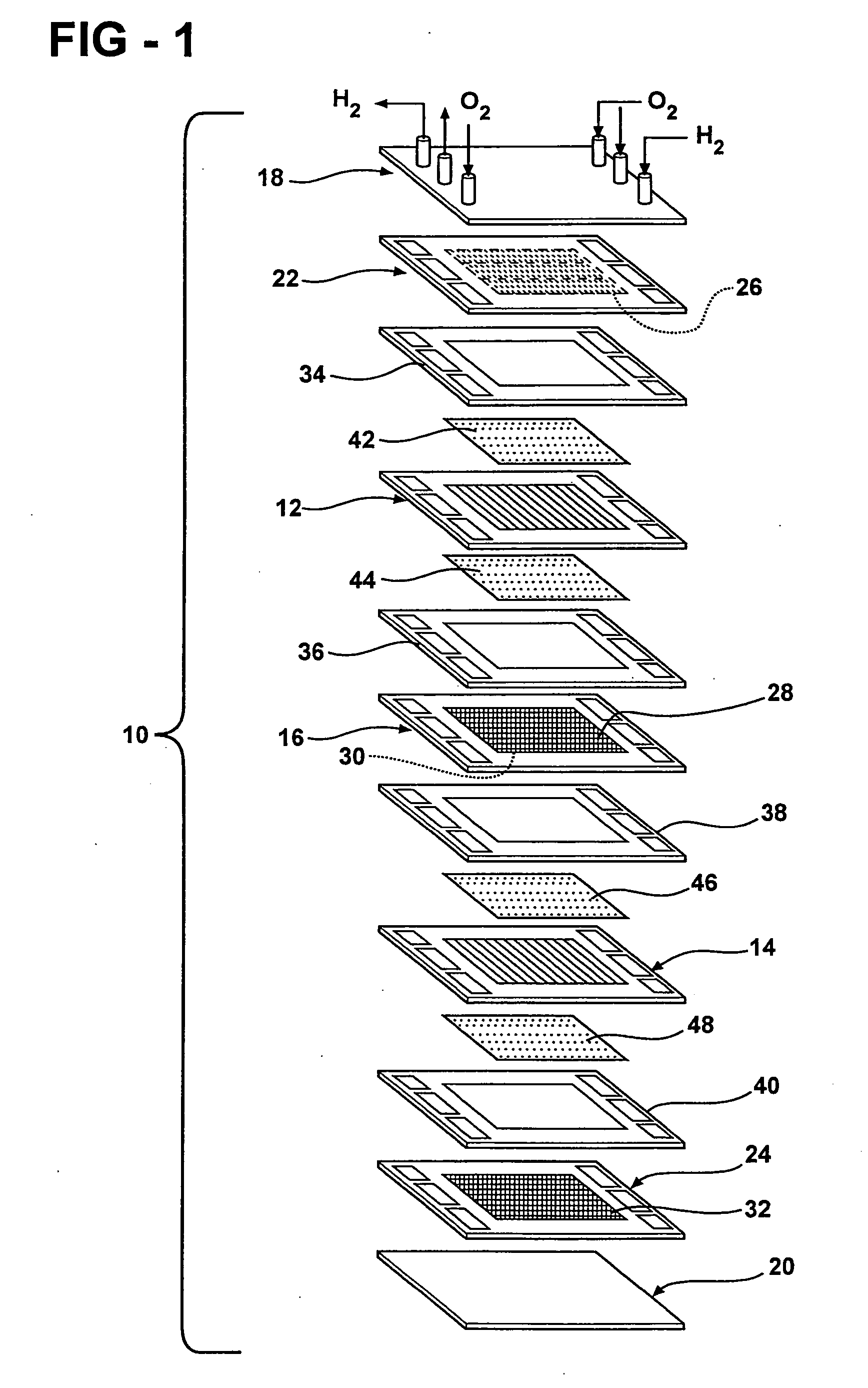
[0025]FIG. 1 shows a two-cell bipolar PEM fuel cell stack 10. Although a bipolar PEM fuel cell stack is shown, it is understood that other fuel cell types and configurations can be used without departing from the scope and spirit of the invention. It is also understood that fuel cell stacks having more cells and plates can be and typically are used.

[0026] The fuel cell stack 10 includes a first membrane-electrode-assembly (MEA) 12 and a second membrane-electrode assembly 14. An electrically conductive, liquid-cooled, bipolar plate 16 is d...


PUM

PropertyMeasurementUnit
lengthsaaaaaaaaaa
lengthaaaaaaaaaa
hydraulic diameteraaaaaaaaaa

Abstract

A system and method of balancing a hydrogen feed for a fuel cell to optimize flow of hydrogen through the fuel cell, wherein a pressure drop through parallel feed channels and active area channels of the fuel cell is balanced.

Description

FIELD OF THE INVENTION [0001] The invention relates to a fuel cell and more particularly to a system and method of balancing a hydrogen feed for the fuel cell to optimize flow of hydrogen through the fuel cell. BACKGROUND OF THE INVENTION [0002] Fuel cell systems are increasingly being used as a power source in a wide variety of applications. Fuel cell systems have been proposed for use in power consumers such as vehicles as a replacement for internal combustion engines, for example. Such a system is disclosed in commonly owned U.S. patent application Ser. No. 10 / 418,536, hereby incorporated herein by reference in its entirety. Fuel cells may also be used as stationary electric power plants in buildings and residences, as portable power in video cameras, computers, and the like. Typically, the fuel cells generate electricity used to charge batteries or to provide power for an electric motor. [0003] Fuel cells are electrochemical devices which directly combine a fuel such as hydrogen...

Claims


Application Information

Patent Timeline
Patent Type & Authority Applications(United States)
IPC IPC(8): H01M8/02H01M4/94B32B3/30
CPCH01M4/8605H01M4/8626H01M8/0234Y10T428/2457H01M8/1002H01M8/241Y02E60/521H01M8/0258H01M8/1007Y02E60/50H01M8/0265H01M8/2483H01M8/2457H01M8/0263H01M8/026
Inventor GOEBEL, STEVEN G.
Owner GM GLOBAL TECH OPERATIONS LLC
Why Eureka
Try Eureka