System and method for gas phase deposition

a technology of gas phase deposition and substrate, which is applied in the direction of electric discharge tubes, coatings, metal material coating processes, etc., can solve the problems of reduced adhesion, degradation of the whole structure, and the grown layer cannot inherit a proper crystalline structure, so as to achieve enhanced control over the gas phase deposition process, good adhesion, and rapid change of process parameters

Inactive Publication Date: 2019-06-13
SINGULUS TECHNOLGIES AG
View PDF0 Cites 7 Cited by
  • Summary
  • Abstract
  • Description
  • Claims
  • Application Information

AI Technical Summary

Benefits of technology

[0088]Various effects may be attained using the systems and methods according to preferred embodiments. The system and method allow three temperatures to be controlled essentially independently within one process chamber. Each temperature can be changed within its process window during a process cycle many times, so as to independently provide good or even optimum conditions for deposition of the desired material. Low thermal mass heaters may be utilized to allow the process parameters to be changed rapidly.
[0089]The enhanced control over the gas phase deposition process allows various effects to be attained. For illustration, if a lower substrate temperature is required to achieve good adhesion or to avoid substrate degradation, the second flow path may still provide a sufficient amount of process gas, which may include a precursor, to the substrate surface to attain good deposition and to provide the energy required for performing chemical reactions on the surface. This similarly applies when lower substrate temperature is required to prevent instability of the grown layer. Because substrate temperature and at least the temperature of the first reactant and precursor gas may be set independently of each other, the system and method according to the disclosure obviate the need to significantly increase the amount of precursor even when the substrate is kept at a lower temperature. Thereby, gas phase reactions may be reduced, which provides benefits in terms of precursor consumption and costs. Further, the quality of the depositing layer may be improved and process chamber efficiency may be enhanced, thereby reducing the frequency of maintenance work, size and costs of the facility equipment.
[0090]The system and method may also be operative to simultaneously deposit material from both the first flow path and the second flow path. This can be done in an efficient way, and turbulences may be eliminated or reduced. Because the enhanced temperature control allows the flow of a component to be reduced compared to conventional systems and methods, the carrier gas flow in at least one of the first and second flow paths may be reduced. This facilitates establishing flow balance.

Problems solved by technology

Gas phase deposition systems and methods which allow only the substrate temperature to be set to provide energy for precursor decomposition, synthesis reaction, and / or alignment of ad-atoms on the substrate surface may have shortcomings because the set temperature may not be optimum for at least one of these processes.
For illustration, one or several of the following shortcomings may be encountered: (1) Nucleation layer growth may have to be performed at a temperature lower than the temperature that would result in the best layer quality, because, for example, higher temperatures would reduce adhesion of atoms on the substrate surface to an unacceptable degree and / or because higher temperatures might destroy the arrangement of atoms and lead to a rough or even amorphous surface, where a grown layer will not be capable of inheriting a proper crystalline structure.
This may lead, in a simple case, to interfaces which are not sharp or to a degradation of the whole structure due to possible physicochemical reactions on the interface.
Precursor efficiency may also be reduced significantly, leading to lower growth rate and / or requiring comparatively larger amounts of material.
The oversupply of one or several precursor components may also create parasitic deposition on surfaces other than the substrate surface, which is undesirable because it may necessitate more frequent cleaning operations.
(4) A higher precursor consumption of only a single precursor or a sub-set of precursors may necessitate flow balance compensation with a carrier gas, thus increasing overall gas consumption.
This in turn may increase process costs.
This may give rise to an increase in production costs.
Further, use of such high substrate temperatures may have adverse effects on the substrate and / or may make it challenging to achieve a uniform temperature.
(6) For various reasons, it may be undesirable to set the substrate temperature to fairly high values.
During a cool down process, the grown structure might reveal cracks and overall shape deformation, rendering it unsuitable for further utilization.
This may allow, for example, an InN compound to be grown with high quality at low temperatures of approximately 500° C. A drawback of plasma activation is the requirement to work under low pressure conditions, e.g., pressures of about 10−2 mbar.
The short life time of ionized species may render plasma less efficient when it has to travel through longer distances, as is the case for remote plasma generation.
The ballistic regime of active ions may lead to mechanical deterioration of the growing surface and the substrate in case of direct plasma and high oxygen content in the film, because of removal of adsorbed oxygen from surfaces of surrounding surfaces, mostly made of metals.
While Plasma Enhanced Deposition (PED) processes may be beneficial, e.g., in case of oxide layers deposition, where oxygen impurity is not a problem, it may not be suitable for other deposition processes where oxygen is not desired.
Due to the ease of evaporation under vacuum conditions the temperature of MBE process may be subject to more severe limitations than higher pressure processes like CVD.
Such undesired, uncontrollable temperature variations would normally be prone to arise when larger recesses need to be provided in the substrate bottom heater or another carrier.

Method used


Image

  • System and method for gas phase deposition
  • System and method for gas phase deposition
  • System and method for gas phase deposition

Examples


Embodiment Construction

[0110]Preferred embodiments of the disclosure will be described with reference to the drawings in which identical or similar reference numerals designate identical or similar elements. The features of the various embodiments may be combined with each other unless explicitly stated otherwise. While some embodiments are described in the context of Metalorganic Vapour Phase Epitaxy (MOVPE) or Metalorganic Chemical Vapour Deposition (MOCVD), the gas phase deposition systems and gas phase deposition methods according to embodiments are not limited thereto.

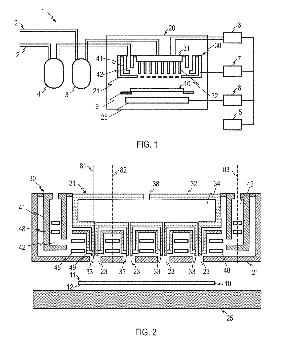
[0111]FIG. 1 shows a system 1 for gas phase deposition according to a preferred embodiment. FIG. 2 shows an enlarged partial cross-sectional view of the gas injector and other components of the system 1.

[0112]The system 1 is operative to deposit one or several different materials onto a substrate 10 in a process chamber 20. The process chamber 20 may be a reactor. As will be explained in more detail below, the system 1 is configured in ...


PUM

PropertyMeasurementUnit
inner diameteraaaaaaaaaa
pressuresaaaaaaaaaa

Abstract

A system for gas phase deposition comprises a gas injector configured to process gases to a substrate for gas phase deposition onto the substrate. The gas injector comprises a first flow path and a second flow path different from the first flow path. The system comprises a first temperature adjustment mechanism associated with the first flow path to control a temperature of a process gas passing through the first flow path. The system comprises a second temperature adjustment mechanism associated with at least the second flow path to control a temperature of a process gas passing through the second flow path. The first temperature adjustment mechanism and the second temperature adjustment mechanism are operable independently of each other. The system is configured to cause rotation and levitation of the substrate during etching of the substrate and/or deposition.

Description

BACKGROUND1. Field of the Disclosure[0001]The present disclosure relates to systems and methods for gas phase deposition onto a substrate. The disclosure relates in particular to systems and methods in which a gas injector directs a process gas onto a surface of a substrate.2. Discussion of the Background Art[0002]Gas phase deposition of material onto a substrate is used for controlled growth and has a wide variety of applications. Gas phase deposition may be used in techniques such as Metalorganic Vapour Phase Epitaxy (MOVPE) or Metalorganic Chemical Vapour Deposition (MOCVD), which can be used for epitaxy. In general, gas phase deposition techniques utilize transport of material towards the substrate surface via free space of pipes, channels and / or reactor volume. Thus, it differs from Liquid Phase Epitaxy (LPE) and Solid Phase Epitaxy or Crystallization. Additional energy may be provided to a surface of a substrate, for example in the form of heat, light or plasma, to trigger che...

Claims


Application Information

Patent Timeline
Patent Type & Authority Applications(United States)
IPC IPC(8): C23C16/52C23C16/458C23C16/455C23C16/46
CPCC23C16/52C23C16/46C23C16/4584C23C16/45574C23C16/4557C23C16/45565H01J37/3244H01J37/32449H01J37/32522H01J37/32715H01J37/32724
Inventor IVANOV, ALEXEYKLEPL, ANDREASRICHTER, JOHANNES
Owner SINGULUS TECHNOLGIES AG
Why Eureka
Try Eureka