Distributed Link Aggregation

a technology of distributed link and aggregation, applied in the field of data communication, can solve problems such as configuration and management challenges, server computers may experience transmission bottlenecks and delays, and may not have the capacity to allocate routing resources, so as to facilitate efficient processing, facilitate workload balancing, and reduce potential bottlenecks

Active Publication Date: 2011-10-27
HEWLETT-PACKARD ENTERPRISE DEV LP
View PDF4 Cites 24 Cited by
  • Summary
  • Abstract
  • Description
  • Claims
  • Application Information

AI Technical Summary

Benefits of technology

[0010]At least one of the embodiments may facilitate workload balancing by distributing routing and link aggregation processes. The distributed routing may reduce pote

Problems solved by technology

For example, contention for routing resources may exist when server computers are housed within racks for space and connectivity considerations, such as in a blade server computer arrangement.
The server computers may experience transmission bottlenecks and delays when forwarding data frames through centralized switches, such as shared top of r

Method used


Image

  • Distributed Link Aggregation
  • Distributed Link Aggregation
  • Distributed Link Aggregation

Examples


Embodiment Construction

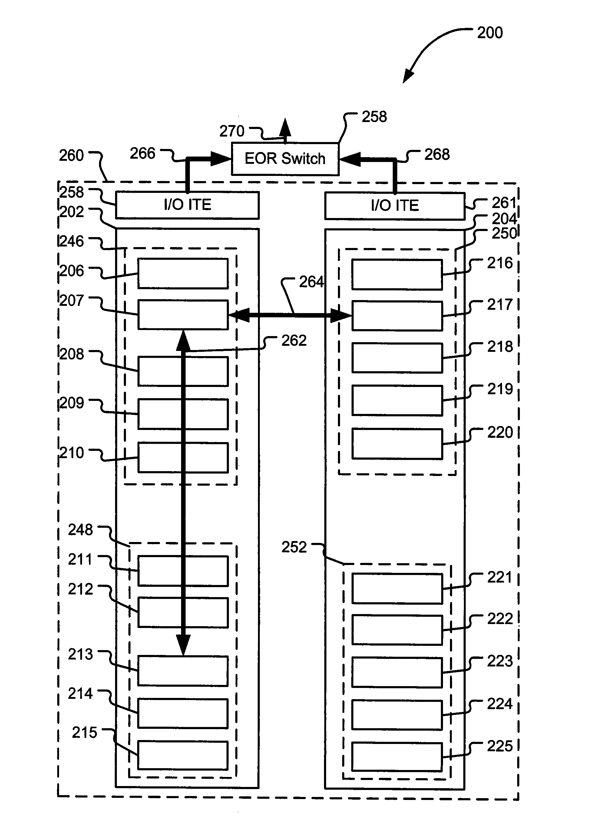
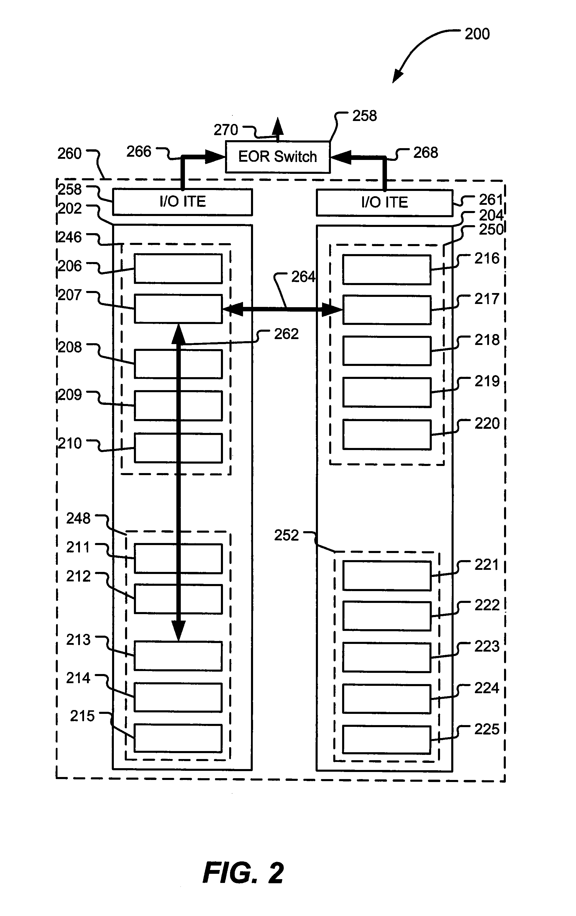
[0018]Data frame communication may be improved by including a distributed aggregator component comprising multiple bridge elements positioned within a highly integrated and scalable network. The distributed bridge elements may comprise part of a distributed virtual bridge that spans multiple server computers. The bridge elements may be configured to perform Layer-2 switching functions. The bridge elements may accomplish operational and frame-forwarding decisions in parallel by distributing load balancing determinations.

[0019]Groupings of ports may be controlled and managed using the distributed virtual bridge. The port groups may span multiple, physically separated server computers to provide external bandwidth. Port group sub-link selection may be performed at the bridge elements. Port group sub-links may use the same external links. Port group and link operational status may be automatically updated within the distributed environment. The link aggregation of port groups may be dis...


PUM


Abstract

Systems and methods to forward data frames are described. A particular method may include generating a plurality of management frames at a controlling bridge. The management frames may include routing information. The plurality of management frames may be communicated to a plurality of bridge elements coupled to a plurality of server computers. The plurality of bridge elements are each configured to selectively forward a plurality of data frames according to the routing information.

Description

I. FIELD OF THE DISCLOSURE[0001]The present disclosure relates generally to data communications, and more specifically, to routing data frames within a highly integrated computer network.II. BACKGROUND[0002]Server computers are continuously managed to enable access to shared switches and other traffic routing resources. For example, contention for routing resources may exist when server computers are housed within racks for space and connectivity considerations, such as in a blade server computer arrangement. The server computers may experience transmission bottlenecks and delays when forwarding data frames through centralized switches, such as shared top of rack switches.[0003]To illustrate, FIG. 1 shows a conventional blade server computer system 100. The system 100 includes a plurality of server computers 106-125 housed within racks 102, 104 and arranged into chassis 138, 140, 142, and 144. An illustrative server computer 106 may include a half-width information technology elemen...

Claims


Application Information

Patent Timeline
IPC IPC(8): H04L12/28
CPCH04L45/245Y02B60/33H04L45/28Y02D30/50
Inventor ARMSTRONG, WILLIAM J.BASSO, CLAUDECORS, JOSEPENGEBRETSEN, DAVID R.LUCKE, KYLE A.LYNCH, JEFFREY J.
Owner HEWLETT-PACKARD ENTERPRISE DEV LP
Why Eureka
Try Eureka