Eureka AIR delivers breakthrough ideas for toughest innovation challenges, trusted by R&D personnel around the world.

Devices for firing a projectile

a projectile and device technology, applied in the direction of firing/trigger mechanism, ammunition, weapons, etc., can solve the problems of device requiring a relatively large charge and long barrel, device can take a relatively long time to be primed for firing, and additional barrel breech does increase the size and weight of the devi

Inactive Publication Date: 2009-02-05
RICHMOND EEI +1
View PDF3 Cites 18 Cited by
  • Summary
  • Abstract
  • Description
  • Claims
  • Application Information

AI Technical Summary

Benefits of technology

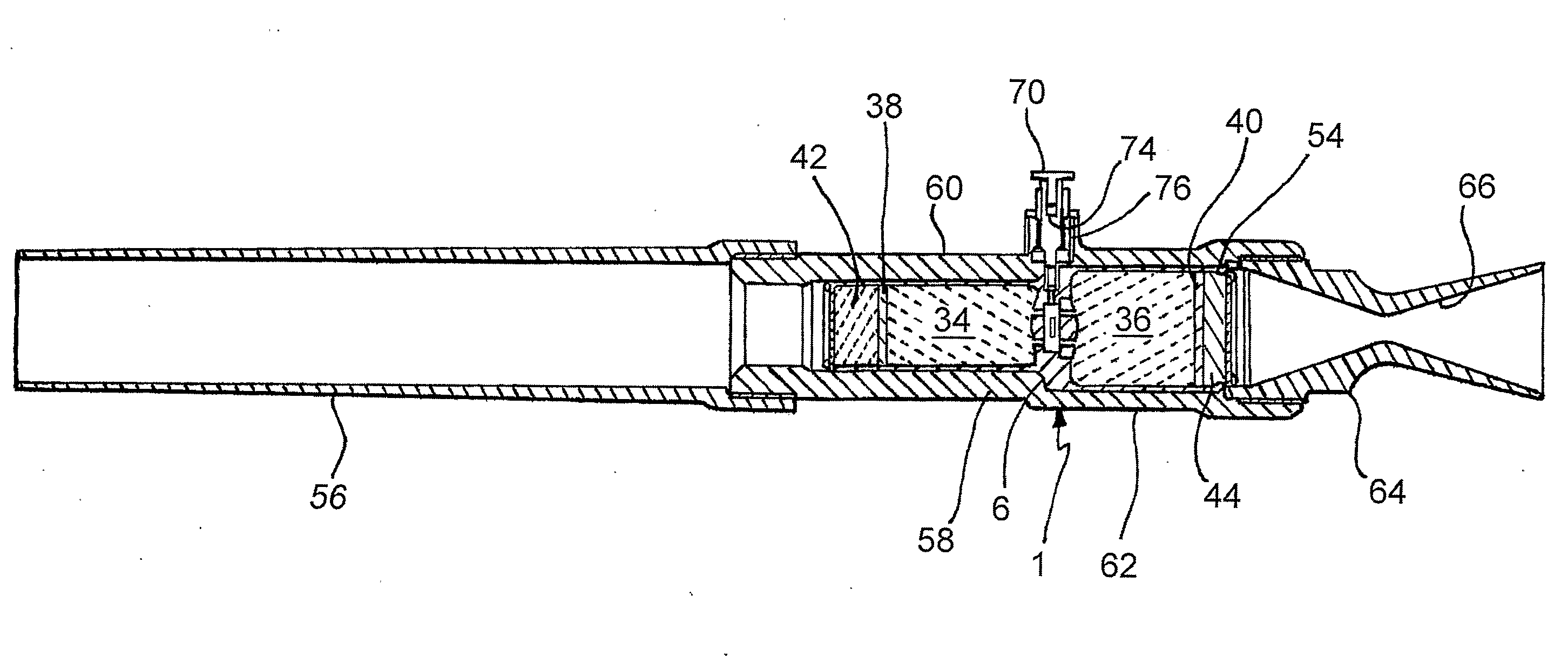
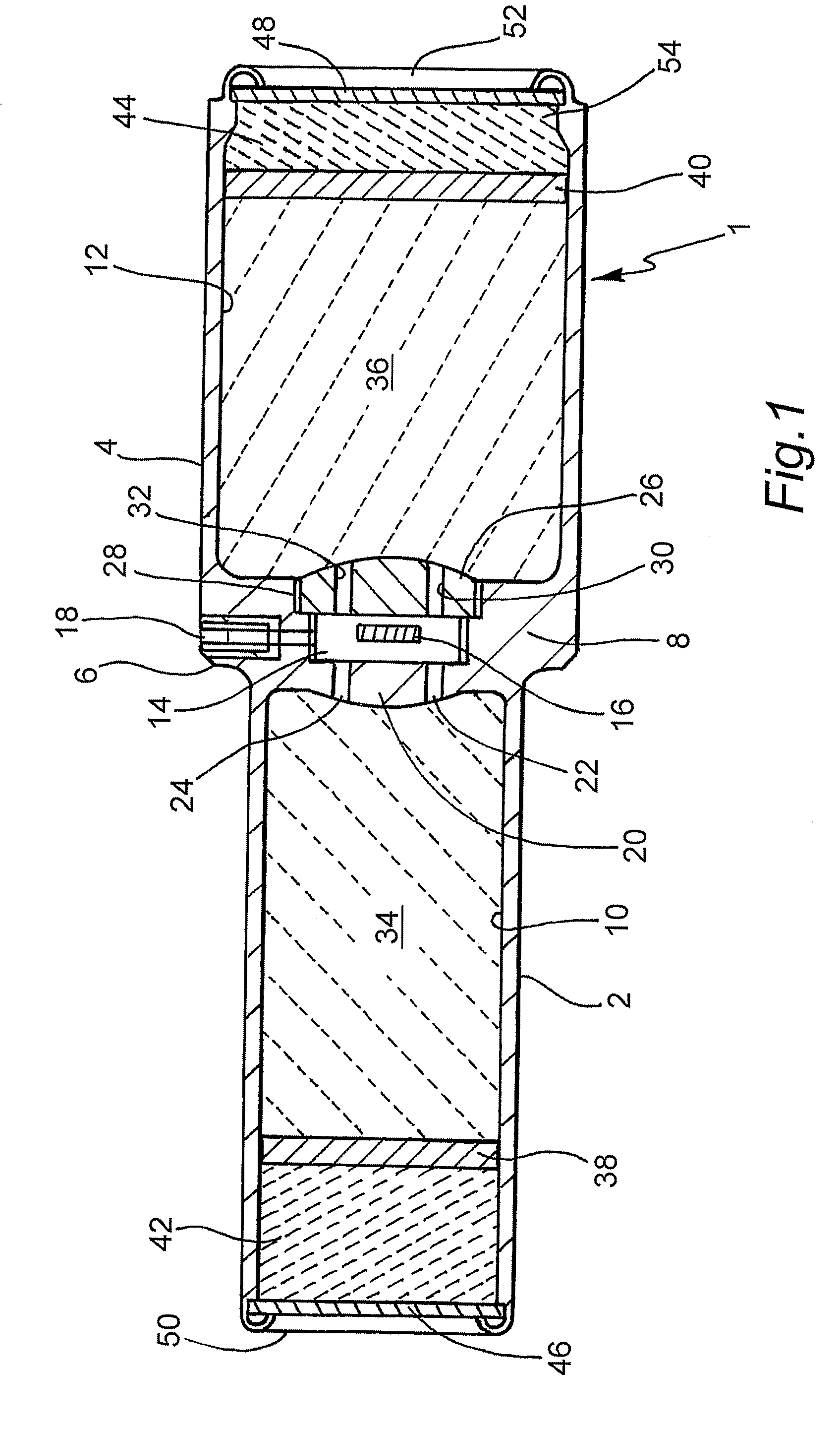
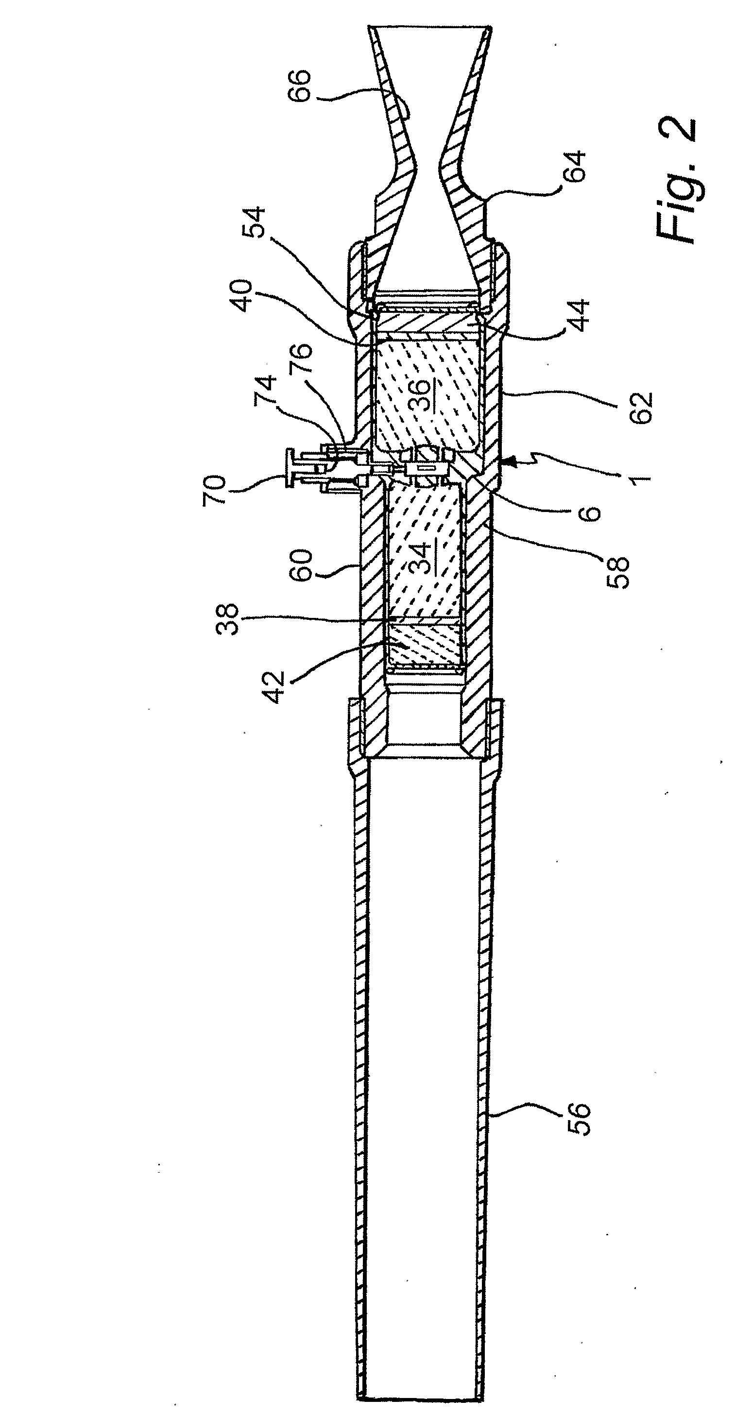
[0009]Since the two charges of propellant, one for firing the projectile, the other for counteracting recoil, are contained in a common cartridge, a device which fires a projectile using that cartridge can have a single breech, and can therefore be more compact and lightweight than a device which uses two separate cartridges. The device is also more compact and lightweight than types of anti-recoil de-armer that do require a jacket of water. Since the propellant charge for firing the projectile is in a separate chamber from that for counteracting recoil, the force with which the projectile is fired is not affected by the gases by which are ejected so as to counteract recoil. Accordingly, the amount of the first propellant charge can be varied independently of the second propellant charge during the stages of design and development of the cartridge. This facilitates the creation of a cartridge which provides a desired force of firing and adequate anti-recoil characteristics. Indeed, it has been found that a cartridge in accordance with the invention can completely neutralise recoil.
[0014]This facilitates the balancing of the device so that the force generated by the rearwardly ejected gases is coaxial with the recoil force caused by the firing of the projectile.
[0017]The reaction forces on the device caused by the exiting projectile are higher than the reaction caused by ejecting gas alone. This is accommodated in the cartridge by increasing the amount and / or velocity of the gases ejected through the outlet of the second chamber compared with those ejected by the detonation of the first charge.
[0020]Consequently, the increased volume of the second chamber does not require an increased length of cartridge.
[0023]This helps to ensure that the detonation of the two charges of propellant material is synchronised.
[0030]This acts as a choke which helps to increase the pressure of gases ejected from the second chamber.

Problems solved by technology

However, these ports reduce the pressure of the gases which are used to propel the projectile, and thus result in the device requiring a relatively large charge and long barrel in order to be able to accelerate the projectile to a sufficiently high velocity.
Although the anti-recoil system of such device does not require a longer primary barrel (for the projectile), the additional barrel breech does increase the size and weight of the device.
Furthermore, the device can take a relatively long time to be primed for firing and it can be difficult to detonate both cartridges simultaneously.
However, the water and the additional components needed for the firing device to contain the water increase the weight of the device, and the need to fill the chamber with water prior to firing the device (and to close the chamber once full) also increases the time needed to prime the device for firing.
However, the upper arm of such a vehicle would not be able to carry a de-armer which weighs more than 1.5 kilograms whereas the various designs discussed above generally weigh at least 3 kilograms.

Method used


Image

  • Devices for firing a projectile
  • Devices for firing a projectile
  • Devices for firing a projectile

Examples


second embodiment

[0058]Turning to FIG. 5 to 7, the cartridge in accordance with the invention has a three part housing formed from two cupped aluminium end pieces 100 and 102 attached one to either side of a central, cylindrical, stainless steel connector 104.

[0059]The cupped piece 102 defines a chamber 106 which contains two propellant charge portions 108 and 110 which correspond to the first propellant charge 34 of the first embodiment. The charge portion 110 is of a relatively slow burning explosive propellant material, whilst the charge portion 108 is of a faster burning explosive material. The two charge portions are separated by a paper disc 112. Similarly, the cupped end piece 100 defines a chamber 114 in which are contained a charge portion 116 of slow burning explosive propellant separated by a paper disc 118 from a charge portion 120 of fast burning explosive propellant. The charge portions 120 and 116 correspond to the second propellant charge 36 of the first embodiment. As can be seen fr...

first embodiment

[0063]The collar 132 also has an internal screw thread 134 via which an externally screw threaded stainless steel plug 136 is attached to the connector 104 to define a bulkhead for the chamber 106. An eccentric axial bore 138 connects the chamber 106 to an ignition chamber 140, which contains an electrical fuse head 142 (similar to the fuse head 16 of the first embodiment). As with the fuse head 16, one side of the fuse head wire is connected to a positive electrical contact 144, the other to earth, and an axial brass ferrule 146 lines the ignition chamber 140.

[0064]The side of the chamber 140 opposite to the plug 136 is provided with a short passage 148 which is concentric with the connector 104, and which leads a dished seat portion 150. The seat portion leads to a small, generally cylindrical gallery 152 which accommodates a valve member 154 comprising a steel ball. The gallery 150 is formed in a stainless steel, axial plug 156 which is provided with a central axial bore 158 situ...


PUM


Abstract

A housing (1; 100, 104, 102) of a cartridge for a device for firing a projectile has separate first and second chambers (10, 12; 106, 114), each of which contains a respective charge (34, 36; 108, 110, 116, 120) of propellant material. Gas produced by the detonation of one of the charges exits the first chamber to propel the projectile, whilst gas from the detonation of the second charge exist rearwardly from the device so as to counteract recoil. A one way valve may also be provided to help to achieve a high pressure difference between the chambers, where the cartridge has a common igniter assembly.

Description

FIELD OF THE INVENTION[0001]This invention relates to a cartridge for a device for firing a projectile and to a device for firing a projectile. Although described in relation to a device for de-arming / disrupting an explosive device, the invention is not limited in application to de-arming and disrupting devices.BACKGROUND TO THE INVENTION[0002]A conventional de-arming device (also referred to as a disrupting device or a de-armer disrupter) operates by firing a solid, liquid or gel projectile at an explosive device so as to disrupt the fuse assembly of the latter, ideally without detonating the explosive device. Such a de-arming device comprises a barrel, the breech of which contains a conventional gun cartridge which, when detonated, propels the projectile, also initially contained in the barrel, towards the target.[0003]It is generally desirable to provide means for reducing the recoil caused by the firing of the projectile, and to that end it is known to fit the end of the barrel ...

Claims


Application Information

Patent Timeline
IPC IPC(8): F41A1/08F42B5/05F42B5/38
CPCF41A1/08F42B5/38F42B5/05
Inventor GILBERT, ROBERT JACKSON
Owner RICHMOND EEI
Why Eureka
Eureka Blog
Learn More