AI technical title is built by Patsnap AI team. It summarizes the technical point description of the patent document.
a robotic arthroplasty and navigation technology, applied in the field of robotic arthroplasty system including navigation, can solve the problems of soft tissue in the knee, difficult access to posterior soft tissue to remove bone spurs (ostified), ligaments in the back of the joint, and/or any residual soft tissue or connective tissue, so as to facilitate the balancing of ligaments
Inactive Publication Date: 2013-08-01
BONUTTI SKELETAL INNOVATIONS
View PDF5 Cites 22 Cited by
Summary
Abstract
Description
Claims
Application Information
AI Technical Summary
This helps you quickly interpret patents by identifying the three key elements:
Problems solved by technology
Method used
Benefits of technology
Benefits of technology
[0018]It is believed that it may be advantageous to utilize an endoscope or a similar apparatus to examine portions of the patient's body which are spaced from the incision. It is also contemplated that images of the knee portion of the patient's leg may be obtained by using any one of many known image generating devices other than an endoscope. The images may be obtained while the patient's leg is stationary or in motion. The images may be obtained to assist a surgeon in conducting any desired type of surgery.
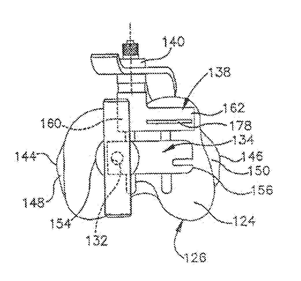
[0019]Balancing of the ligaments in the knee portion of a patient's leg may be facilitated by the positioning of one or more transducers between tendons, ligaments, and / or bones in the knee portion. One transducer may be positioned relative to a medial side of a knee joint. Another transducer may be positioned relative to a lateral side of the knee joint. During bending of the knee joint, the output from the transducers will vary as a function of variations in tension forces in the ligaments. This enables the tension forces in ligaments in opposite sides of the knee portion to be compared to facilitate balancing of the ligaments.
Problems solved by technology
This results in the soft tissue in the knee being compressed against the back of the knee joint.
This makes it very difficult to access posterior soft tissue to remove bone spurs (ostified), meniscus, posterior capsule, ligaments in the back of the joint, and / or any residual soft tissue or connective tissue that is blocking further flexion.
Therefore, a surgeon may be very reluctant, or at least very careful, of inserting instruments into the back of the knee joint to remove tissue.
This may result in osteophytes, bone spurs and similar types of posterior soft tissue being left in place.
Moving the everted patella to one side of end portions of the femur and tibia tends to increase the size of the incision which must be made in the knee portion of the patient's leg.
However, the checking of ligament balance by flexing and extending the leg of the patient, ignores rotational balancing of ligaments.
Method used
Image
Click on the blue label to locate the original text in one second.
Reading with bidirectional positioning of images and text.
Examples
Embodiment Construction
Known Method of Performing Surgery on a Patient's Knee
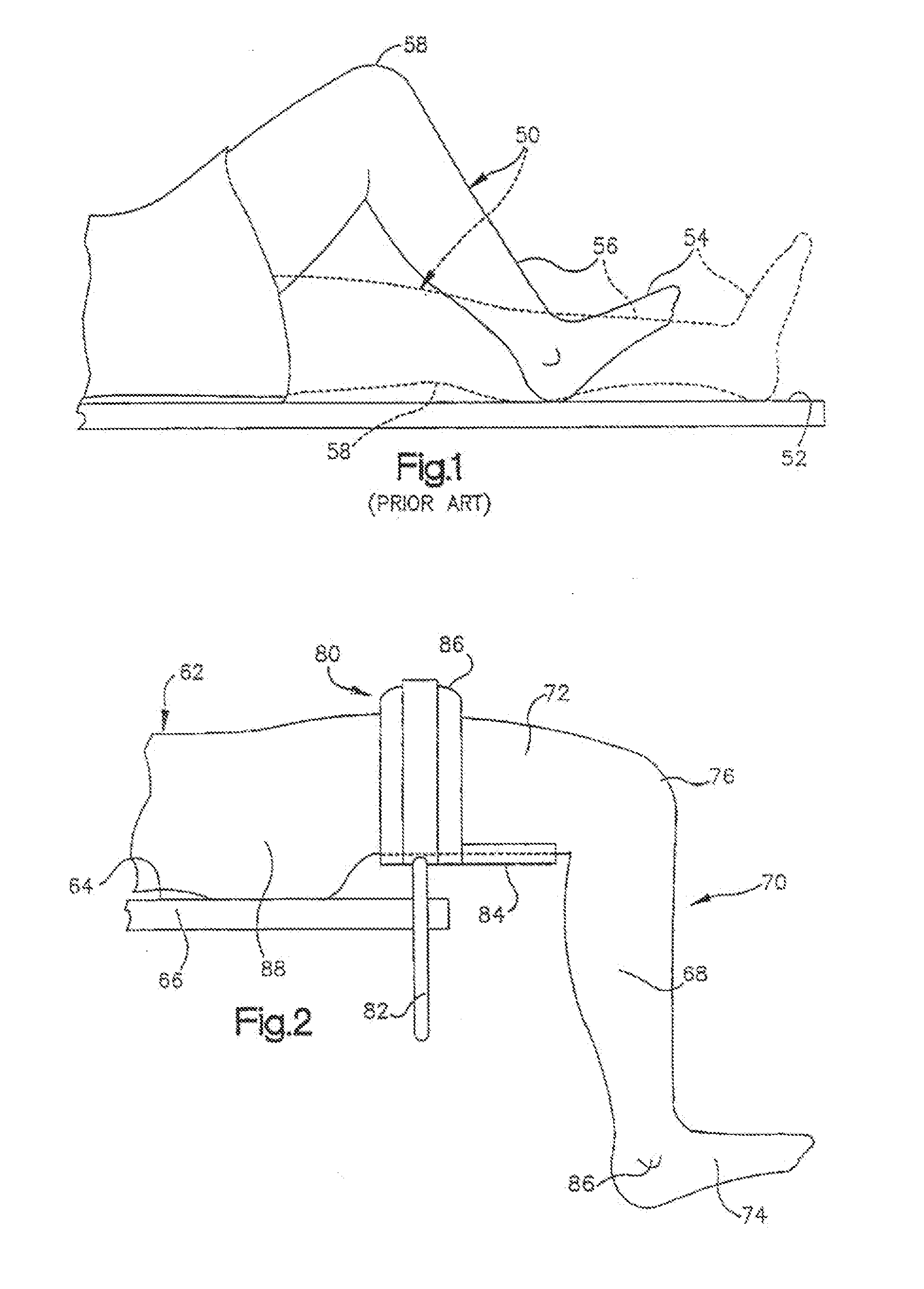
[0131]During the performance of surgery using known methods, a patient is supported on an operating table or other support surface 52 (FIG. 1). When a leg 50 of the patient is in the extended position illustrated in dashed lines in FIG. 1, a foot 54 connected with a lower portion 56 of the leg 50 is disposed above the support surface 52. During an operation on a knee portion 58 of the leg 50, the knee portion is raised and lowered relative to the support surface as the leg 50 is flexed and extended. However, the foot 54 is always disposed above the support surface 54 and may be supported by the support surface throughout the operation.
[0132]During this known operating procedure, an incision is made in the knee portion 58 of the leg 50 when the leg is in the extended position illustrated in dashed lines in FIG. 1. At this time, the foot 54 of the patient may rest on the support surface 52 or be disposed in a foot support located a...
PUM
Property
Measurement
Unit
angle
aaaaa
aaaaa
included angle
aaaaa
aaaaa
length
aaaaa
aaaaa
Abstract
A system for performing surgery on a femur and tibia of a knee joint. The system includes a robotic subsystem; a navigation subsystem in communication with the robotic subsystem; a control unit in communication with the robotic subsystem; and a display in communication with the control unit. The navigation subsystem provides the robotic subsystem with information relating to positions of the femur and tibia thereby enabling their separate tracking when the femur and tibia move during surgery. The navigation subsystem cooperates with the robotic subsystem to determine a position of the cutting tool relative to the femur and tibia to guide movement of the cutting tool to cut away material from the femur and tibia. The control unit receives information relating to the position of the cutting tool such that movement of the cutting tool relative to the femur and tibia during surgery is viewable on the display.
Description
CROSS-REFERENCE TO RELATED APPLICATIONS[0001]This application is a continuation of U.S. patent application Ser. No. 13 / 407,968 filed Feb. 29, 2012. U.S. patent application Ser. No. 13 / 407,968 is a continuation of U.S. patent application Ser. No. 13 / 407,448 filed Feb. 28, 2012. U.S. patent application Ser. No. 13 / 407,448 is a continuation of U.S. patent application Ser. No. 13 / 221,033 filed Aug. 30, 2011. U.S. patent application Ser. No. 13 / 221,033 is a continuation of U.S. patent application Ser. No. 12 / 795,935 filed Jun. 8, 2010. U.S. patent application Ser. No. 12 / 795,935 is a continuation of U.S. patent application Ser. No. 11 / 684,103 filed Mar. 9, 2007, now U.S. Pat. No. 7,828,852. U.S. patent application Ser. No. 11 / 684,103 is a continuation of U.S. patent application Ser. No. 10 / 681,526 filed Oct. 8, 2003, now U.S. Pat. No. 7,635,390. U.S. patent application Ser. No. 10 / 681,526 is a continuation of U.S. patent application Ser. No. 10 / 191,751 filed Jul. 8, 2002, now U.S. Pat. N...
Claims
Application Information
Patent Timeline
Application Date:The date an application was filed.
Publication Date:The date a patent or application was officially published.
First Publication Date:The earliest publication date of a patent with the same application number.
Issue Date:Publication date of the patent grant document.
PCT Entry Date:The Entry date of PCT National Phase.
Estimated Expiry Date:The statutory expiry date of a patent right according to the Patent Law, and it is the longest term of protection that the patent right can achieve without the termination of the patent right due to other reasons(Term extension factor has been taken into account ).
Invalid Date:Actual expiry date is based on effective date or publication date of legal transaction data of invalid patent.
Patent Type & AuthorityApplications(United States)

