Travel banjo

a technology for banjos and travel instruments, applied in banjos, stringed musical instruments, musical instruments, etc., can solve the problems of compromising the effective of their practice time, affecting playability, portability, durability, and sound quality, and achieve the effect of convenient compact storage and transportation

Inactive Publication Date: 2005-10-27
FARRIS SAMUEL DAVID
View PDF5 Cites 9 Cited by
  • Summary
  • Abstract
  • Description
  • Claims
  • Application Information

AI Technical Summary

Benefits of technology

The invention aims to provide a way to remove the neck of a device without using tools or string removal. This makes the device easier to store and transport.

Problems solved by technology

The technical problem addressed in this patent is how to create a small, lightweight travel banjo with a full range of notes while maintaining its musical performance and ease of playability compared to larger instruments. Additionally, there may be various ways to modify the appearance and functionality of the instrument depending on the preferences of players and users.

Method used


Image

  • Travel banjo
  • Travel banjo
  • Travel banjo

Examples


Embodiment Construction

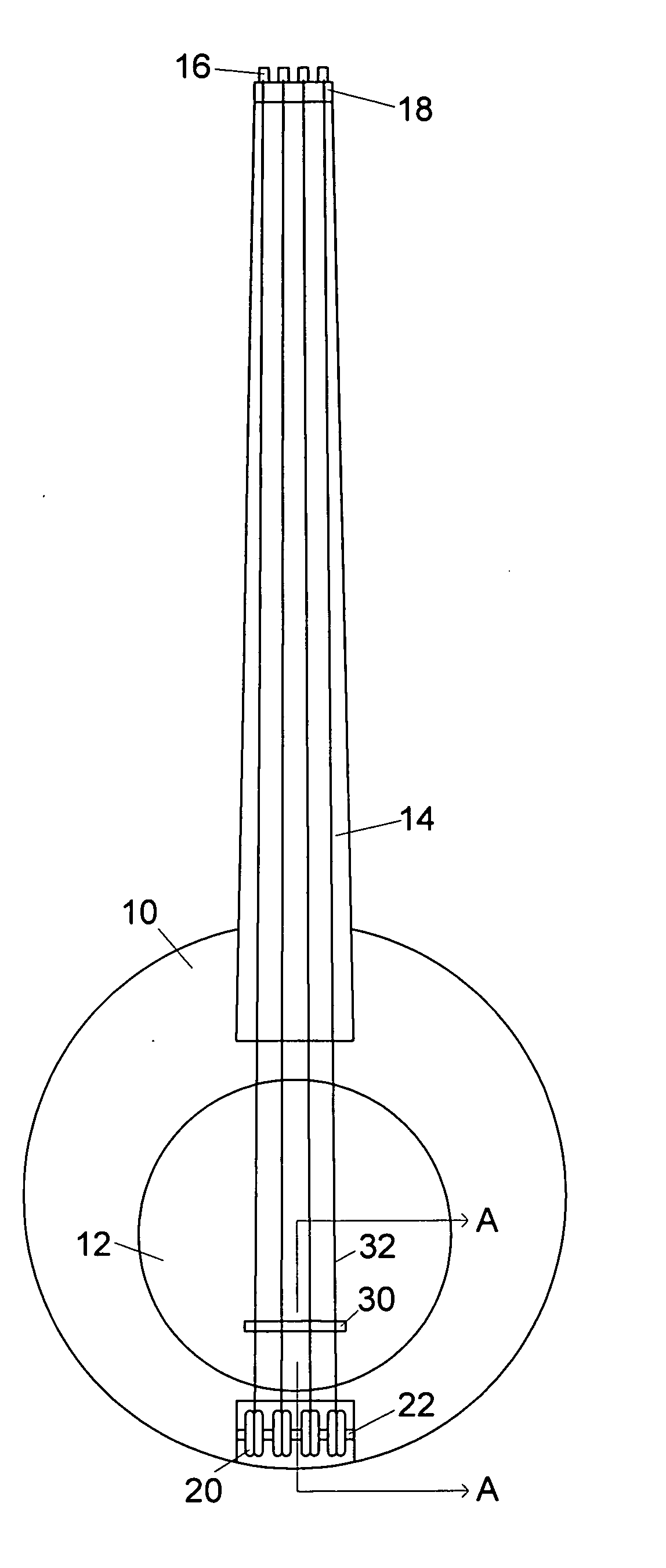
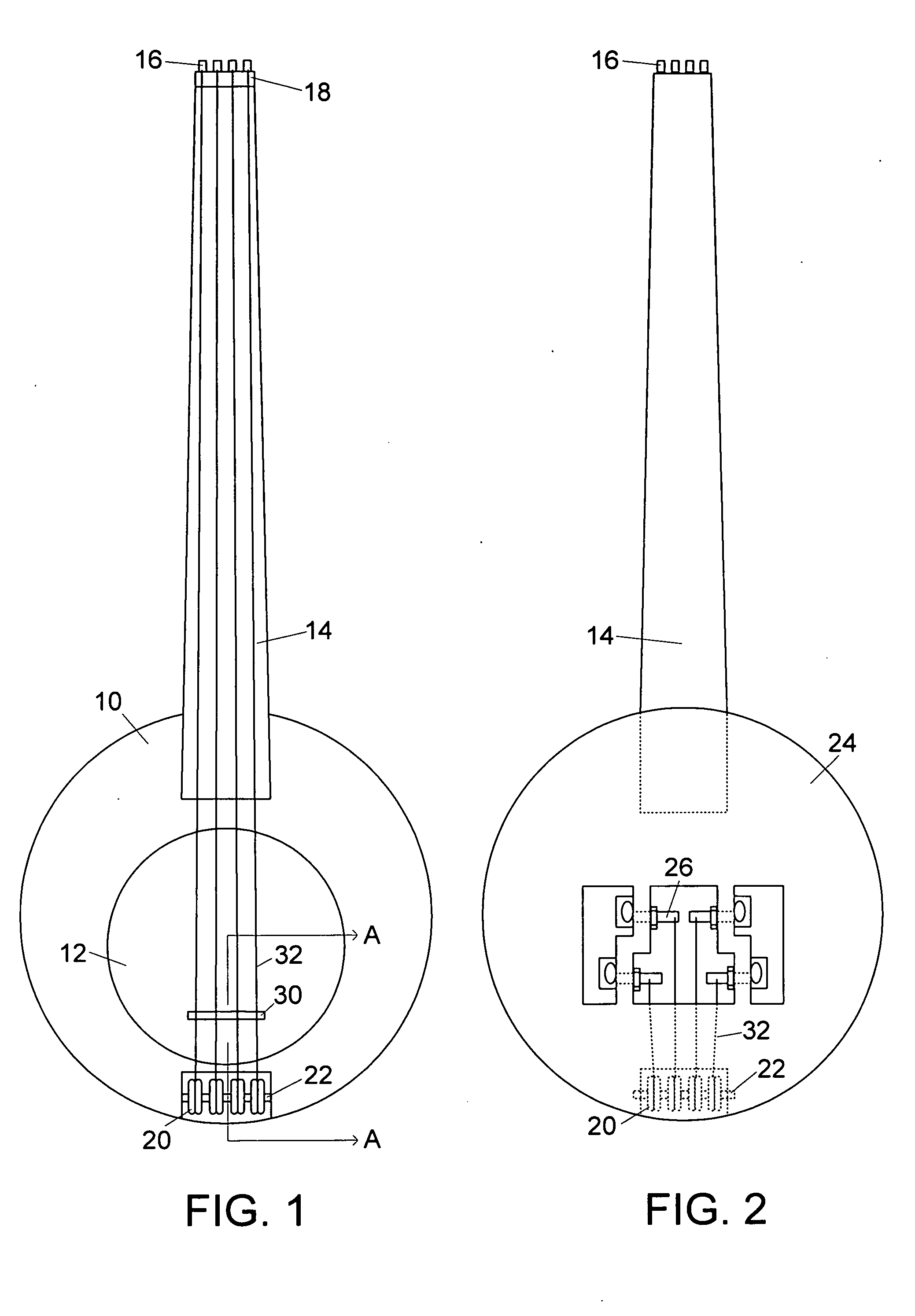
[0035] This is a stringed musical instrument, commonly referred to as a banjo, shown assembled in FIG. 1 (front view) and FIG. 2 (rear view). The main sounding surface consists of a standard head assembly 12, such as found in a conventional banjo or drum, upon which rests a moveable bridge 30. The bridge 30 is held in place by the tension of the string 32, each of which stretches from a post 16 at the end of the neck 14, over a nut 18, to a roller 20 mounted on an axle 22 at the other end of the instrument. Each roller 20 redirects a string 32 to a standard guitar-type tuning mechanism 26 on the body of the instrument, which consists of a front body plate 10 and a rear body plate 24. The neck 14 may be fretted or unfretted as desired, according to standard musical instrument design.

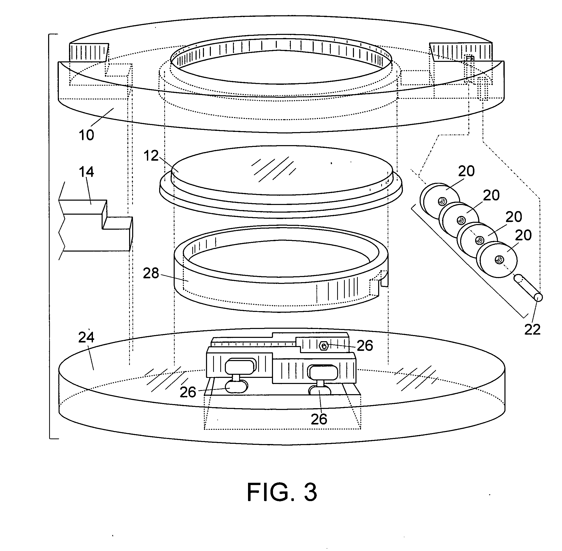
[0036]FIG. 3 shows an exploded view of the assembly of the instrument. This design eliminates most of the specialized hardware found on a conventional banjo. Tension is applied to the membrane portion of...


PUM


Abstract

A travel banjo optimized for sound quality, portablity and ruggedness. The neck, fingerboard and string scale are identical to a regular banjo. The neck is attached to the body with a thumbscrew. The body consists of a front and back plate which are fastened together mechanically. A commercial drum head is tensioned by the force of the front and back plates being drawn together, applying pressure to the head and the tone ring. A string clamp is attached by a thumbscrew to retain the strings and bridge in when the neck is removed. The strings are attached to string posts at the end of the neck travelling over the bridge to a set of rollers, which redirect the string path to the rear where the tuning mechanisms are mounted in a protected area. The head and bridge are similar to a regular banjo to provide an authentic banjo sound.

Description


Claims


Application Information

Patent Timeline
Owner FARRIS SAMUEL DAVID
Why Eureka
Try Eureka