Building escape system

a technology of building escape and ladder, which is applied in the direction of building lifts, constructions, building constructions, etc., can solve the problems of excessive flexibility, and difficult unfurling of the structure, so as to minimize the accessability of the aligned apertur

Inactive Publication Date: 2012-03-20
ASHMUS JAMES L
View PDF79 Cites 2 Cited by
  • Summary
  • Abstract
  • Description
  • Claims
  • Application Information

AI Technical Summary

Benefits of technology

[0008]Another object of the invention is to provide an escape system incorporating an endless ladder-like device which is sufficiently flexible to facilitate compact storage while being sufficiently fixed in its form to facilitate unfurling and stability of position during usage in an emergency.
[0032]Some embodiments of the inventive escape system further include a railing extending along at least a portion of a building perimeter, and a frame movably connected to the railing. The support structure is preferably secured with respect to the frame such that the belting ladder may be moved to a necessary position along the building for emergency evacuation. The railing may be in a form of an I-beam including rollers along its length. This provides great flexibility for use of the escape system which would allow a single ladder to serve a large portion of a building facade, such that in case of emergency the ladder may be moved to a necessary location via the railing.

Problems solved by technology

For some devices, collapsing for compact storage is problematic or has disadvantages.
There may be difficulty in unfurling the structure for use in a time of emergency, with susceptibility to problems such as tangling.
Certain prior disclosures of flat band devices have problematic slit-like features which can tend to pose difficulties for persons trying to lower themselves—problems related to difficulty in securing proper foot engagement with the device.
Excessive flexibility is another problem, as is limited capability for dealing concurrently with multiple persons seeking to escape, e.g., from a burning building.
Furthermore, it is noted that potential revisions of prior structures for the purpose of alleviating certain problems can introduce or exacerbate other problems.
An important issue for any escape ladder is its immediate availability in fully operative condition in case of emergencies, which may happen decades after installation.
Certain collapsible ladders may tend not to withstand long-term outdoor storage because of being susceptible to rot, rust and other types of destruction.

Method used


Image

  • Building escape system
  • Building escape system
  • Building escape system

Examples


Embodiment Construction

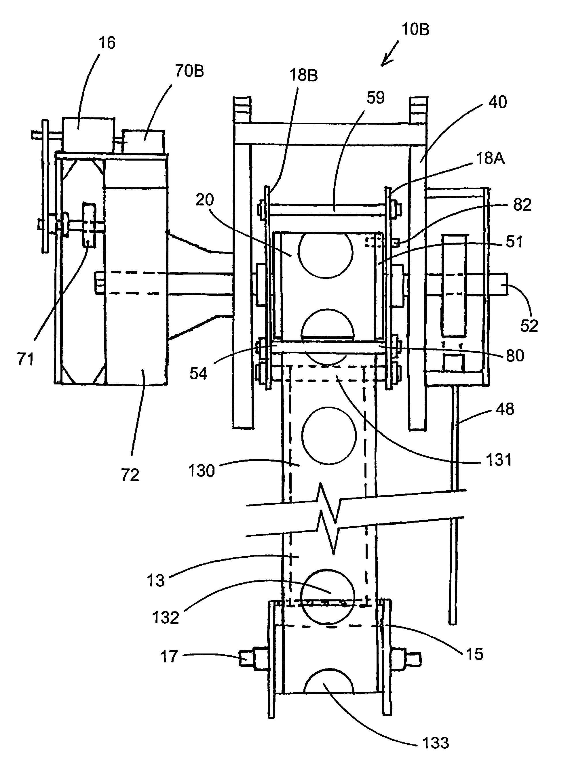
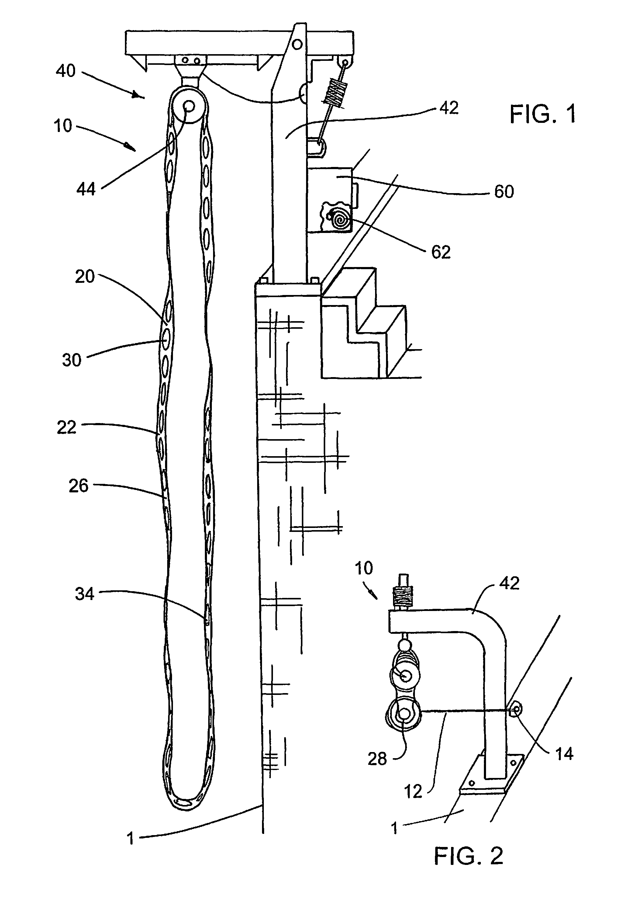
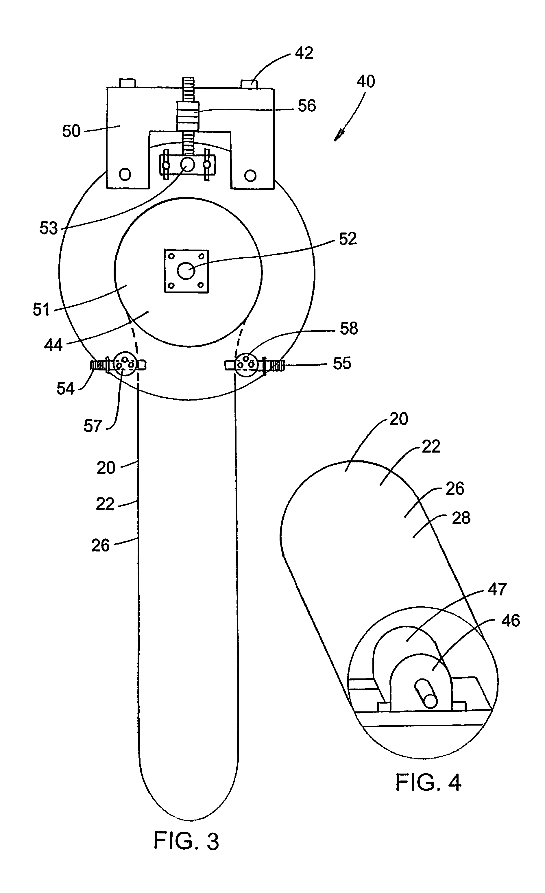
[0053]FIGS. 1-12 illustrate an inventive escape system 10 for a building 1. Referring to the figures, inventive escape system 10 includes an endless belting ladder 20 formed by an endless elongated band 22 with a width 24 of a flat flexible reinforced belting material 26 having a plurality of longitudinally-spaced apertures 30 each with a substantially transverse edge portion 32 thereby forming rung-like features 34 along belting material 26 to receive a person's foot or hand; and a control apparatus 40 (for convenience also referred to as a pulley system 40) having a support structure 42 mountable to building 1, at least one substantially cylindrical member 44 rotatably secured with respect to support structure 42, and a speed limiter 46 controlling the rotation of cylindrical member 44. Endless band 22 is secured around cylindrical member 44.

[0054]As seen on FIG. 4 speed reducer 46 is a gear box 47 set for a maximum speed controlling descending movement of belting ladder 20.

[0055]...


PUM


Abstract

An escape system for a building, including a belting ladder formed by an endless band of a flat flexible reinforced belting material with a plurality of longitudinally-spaced apertures each with a substantially transverse edge portion forming rung-like features therealong for human engagement, and a control apparatus having (a) a support structure mountable to the building, the support structure having a central shaft and a rotatable pulley member secured thereto with the endless band therearound, (b) a speed limiter mounted with respect to the main shaft for restraining rotation of the pulley member during human descent by belt movement. In some embodiments, the control apparatus also includes a winder device adjacent to the pulley member and having at least one winder rod engageable with the belt and orbitable with an engaged portion thereof about the pulley member.

Description

RELATED APPLICATIONS[0001]This application is a continuation-in-part of U.S. application Ser. No. 11 / 207,445, filed on Aug. 19, 2005 (the contents of which are incorporated herein by reference); and this application is also a continuation of U.S. application Ser. No. 12 / 036,133, filed on Feb. 22, 2008 (the contents of which are incorporated herein by reference), which is based in part on U.S. Provisional Application No. 60 / 902,687, filed Feb. 22, 2007 (the contents of which are incorporated herein by reference).FIELD OF THE INVENTION[0002]The present invention relates to flexible ladders for emergency escape from buildings.BACKGROUND OF THE INVENTION[0003]A variety of flexible ladders and the like have long existed for use in various emergency situations, a prime example of which is use for escape from burning buildings. Among other things, the prior art includes a variety of rope ladders, ladders with rigid rungs connected by ropes or chains, flat bands intended for use in descendi...

Claims


Application Information

Patent Timeline
Patent Type & Authority Patents(United States)
IPC IPC(8): E06C1/56
CPCA62B1/08A62B1/10
Inventor ASHMUS, JAMES L.
Owner ASHMUS JAMES L
Why Eureka
Try Eureka