
Portable electronic device

Active Publication Date: 2005-10-27
INVENTEC CORP
View PDF13 Cites 29 Cited by
  • Summary
  • Abstract
  • Description
  • Claims
  • Application Information

AI Technical Summary

Benefits of technology

[0009] In light of the above drawback in the prior art, a primary objective of the present invention is to provide a portable electronic device having a display screen thereof being freely turned in any direction and set at any angle to provide a comfortable viewing position for a user.
[0012] Furthermore, in another embodiment, the portable electronic device is a tablet electronic device having a display screen. A universal holder member is mounted below the tablet electronic device, and allows the display screen of the tablet electronic device to be adjusted in forward and backward, lateral, and / or horizontal directions to a suitable viewing position for the user.

Problems solved by technology

However, the notebook computers are still not perfect and have a significant drawback.
In some occasions, such as at the outdoors or in a car, there is no flat desk to support the notebook computer such that the LCD may not be positioned properly facing the user, making the notebook computer not convenient to operate.
The holder device 20 cannot be structurally foldable, which is also a disadvantage for portable use.
However, such holder device is fixed in position when being in use though it allows the user to operate the notebook computer in the car, such that this holder device is not suitable for use in any location or at the outdoors without being fixed in position.

Method used


Image

  • Portable electronic device
  • Portable electronic device
  • Portable electronic device

Examples


first preferred embodiment

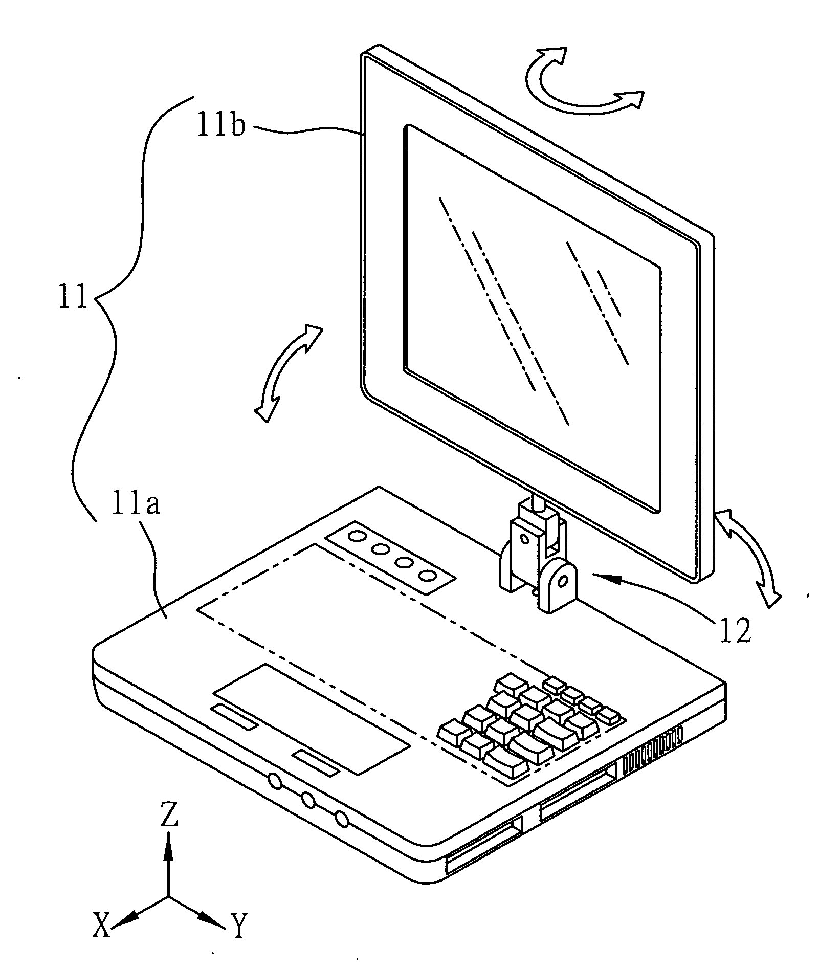
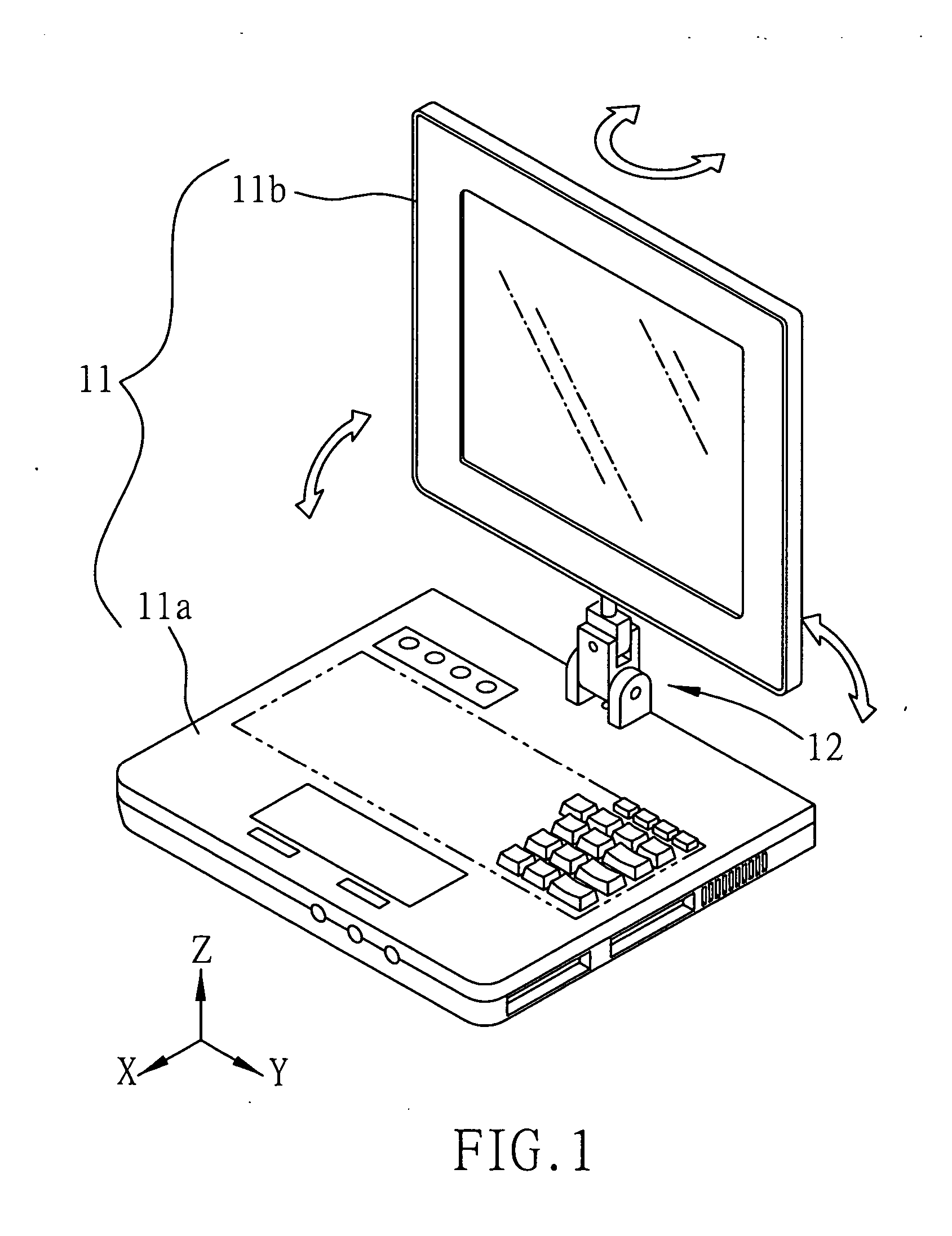
[0020]FIG. 1 shows a portable electronic device according to a first preferred embodiment of the present invention. The portable electronic device may be any electronic device having two main interconnected parts capable of being opened or closed from or to each other, customarily referred to as flip-top electronic device 11, for example notebook computer, laptop computer, portable computer, flip-top dictionary, flip-top cellular phone, or flip-top calculator. The electronic device 11 comprises a host 11a and a display unit such as display screen 11b. A universal pivotal member 12 is pivotally mounted between the host 11a and the display screen 11b, and can be operated in three axial directions so as to position the display screen 11b at a suitable orientation.

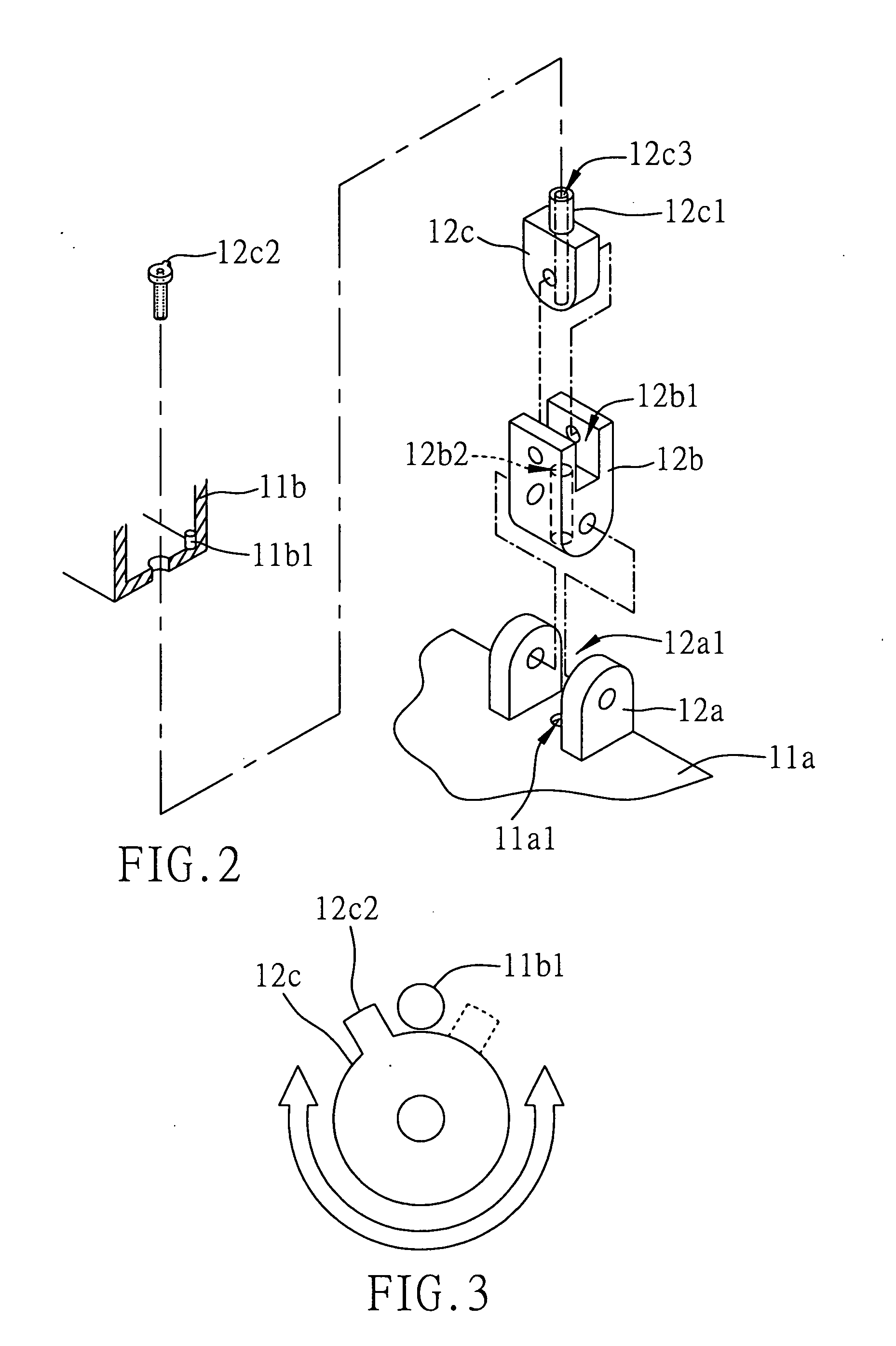
[0021]FIG. 2 shows an exploded view of the universal pivotal member 12 according to the present invention. The universal pivot member 12 comprises a mount 12a mounted on the host 11a, a first shaft component 12b and a second ...

second preferred embodiment

[0026]FIG. 4 shows a portable electronic device according to a second preferred embodiment of the present invention. The portable electronic device in this embodiment can be a tablet electronic device 13 having a display unit e.g. display screen. The tablet electronic device 13 can be a tablet PC (personal computer), palmtop computer, tablet electronic dictionary, tablet calculator, or personal digital assistant (PDA). A universal holder member 14 is mounted below the tablet electronic device 13. The universal holder member 14 comprises a base 14a and a mount 14b provided on the base 14a. The mount 14b has an opening 14b1 where a first shaft component 14c is pivotally mounted in a manner that the first shaft component 14c can swing back and forth. The first shaft component 14c has a recess 14c 1 where a second shaft component 14d is pivotally mounted in a manner that the second shaft component 14d can laterally swing. A rotatable clip 14d1 is provided at the top of the second shaft ...


PUM


Abstract

A portable electronic device includes a host, a display screen and a universal pivot member. The universal pivot member is mounted between the host and the display screen and can freely rotate to adjust the display screen to a comfortable viewing position for a user. In another embodiment, the portable electronic device includes a host having a display screen, and a universal holder member mounted below the host. The universal holder member can similarly freely rotate to adjust the display screen of the host to a comfortable viewing position for the user.

Description

FIELD OF THE INVENTION [0001] The present invention relates to portable electronic devices, and more particularly, to a portable electronic device having a display screen thereof capable of being turned in any direction and adjusted to a comfortable viewing position. BACKGROUND OF THE INVENTION [0002] Along with the advancement in the computer technology, for the sake of providing more operational convenience for users, computers have been evolved from desk-top computers to notebook computers that are portable and widely accepted by the users. However, the notebook computers are still not perfect and have a significant drawback. For example, when using the notebook computer, a liquid crystal display (LCD) of the notebook computer must be deployed from a notebook main body and is usually adjusted in position by the user to a suitable view angle where text and / or pictures on the LCD can be seen. In some occasions, such as at the outdoors or in a car, there is no flat desk to support t...

Claims


Application Information

Patent Timeline
IPC IPC(8): G06F1/16H05K7/16
CPCG06F1/1616G06F1/1622Y10S248/92Y10S248/919Y10S248/917G06F1/1681
Inventor YU, CHRISTINE
Owner INVENTEC CORP
Learn More