
Gauze pad holder for post-surgical intraoral use

a post-surgical and intraoral technology, applied in the field ofgauze pad holders, can solve the problems of reducing the safety of patients, and reducing so as to reduce the risk of dislodgement, avoid antibiotic resistance bacteria, and stabilize blood clots.

Active Publication Date: 2017-12-14
TALA SURGICAL INC
View PDF0 Cites 2 Cited by
  • Summary
  • Abstract
  • Description
  • Claims
  • Application Information

AI Technical Summary

Benefits of technology

This invention is a gauze pad holder for use in dental procedures. It is designed to hold gauze pads in a safe, hygienic and sanitary way. It prevents exposure to antibiotic-resistant bacteria after surgical procedures, minimizes bleeding and helps stabilize the blood clot in the tooth socket. It also helps to prevent choking and avoids the need for direct hand contact with the patient, providing a sense of security and comfort. The holder is easy to use, remove or substitute after being used. Additionally, it has an extra locking mechanism and is ergonomically designed for different dental positions. Overall, this invention provides a better and safer method for using gauze pads in dental procedures.

Problems solved by technology

Surgical procedures inside the mouth, such as tooth extractions, generally cause more bleeding than a skin wound due to the difficulty associated with the process of drying out the gums and thus delaying the blood clot formation, which is an essential initial step of the post extraction healing process.
Unfortunately, due to different factors, the blood clot at the site of the tooth extraction is not always properly formed and / or developed.
As a consequence, there is an exposure of the underlying bone and nerves to air, food, fluid, bacteria or any other potential organisms that results in intense pain, not only in the socket but also along the nerves radiating to the side of your face.
This represents a poor hygienic practice that exposes the surgical area to potential pathogens such as bacteria, increasing the chances of opportunistic infections and other postsurgical complications.
Another potentially dangerous situation is due to the fact that the gauze pad is not secured by any means inside the oral cavity of a patient who is generally under some kind of sedation, said gauze pad may be displaced from the surgical area to the patient's pharynx, causing an obstruction of the patient's airway; thus representing and asphyxiation or choking hazard.
Furthermore, since the patient has no direct visual contact of the surgical site's exact location, there is a high chance that he or she may not be able to place and maintain the gauze pad in the proper location, thus the effect of applying pressure over the desired and specific intraoral area may not be achieved.
In a similar manner, after using said gauze pad, it is uncomfortable and unpleasant to remove it from the mouth, since it is soaked with blood and saliva.

Method used


Image

  • Gauze pad holder for post-surgical intraoral use
  • Gauze pad holder for post-surgical intraoral use
  • Gauze pad holder for post-surgical intraoral use

Examples


first embodiment

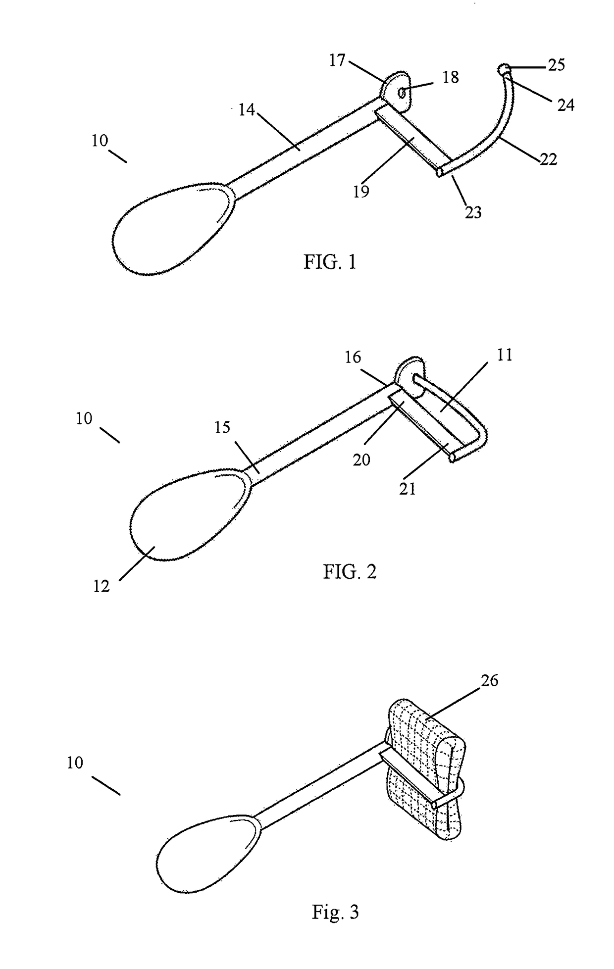
[0066]the invention 10 is illustrated in FIG. 1 in open position; in FIG. 2 in a closed position, in order to show the internal cavity or chamber, wherein the gauze pad may be held and secured and in FIG. 3, wherein it has already a gauze pad assembled, held and secured in its internal cavity or chamber 11.

[0067]Particularly and as illustrated in FIGS. 1 and 2, it comprises a handle section 12, which is illustrated having a preferably flat, oval shape with a concave center surrounded by round edges; although it may have any other suitable shape. Extending from handle section 12, it also comprises connecting section 14, which has an elongated body, having a preferably cylindrical shape; a first end 15, wherein it is connected to handle 12 and a second end 16, which it is connected to first holding section 17.

[0068]First holding section 17 comprises a flat main body, having aperture 18 at the center or substantially the center of said main body of first holding section 17. Thus, first...

embodiment 27

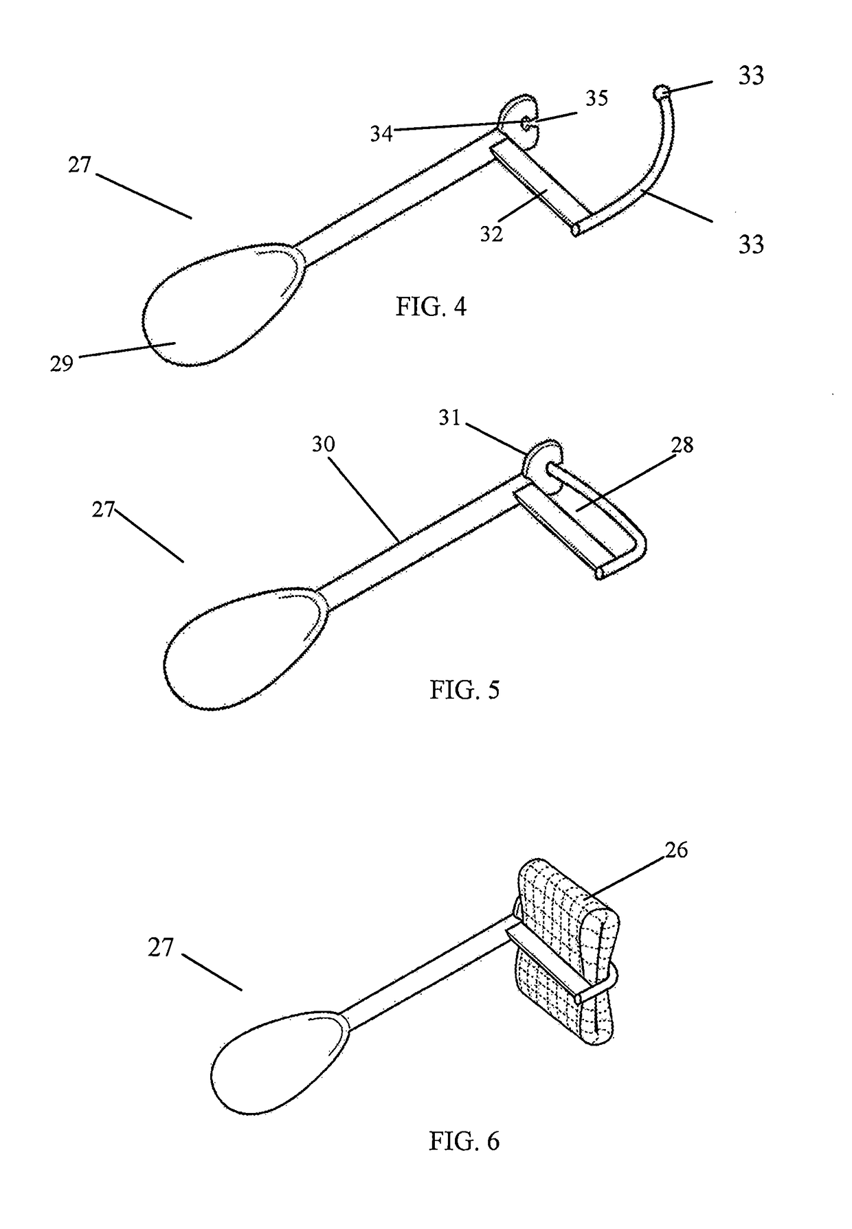
[0072]As illustrated in FIGS. 4 and 5, first holding unit 31 comprises a main flat body having a round aperture 34 at the center or substantially the center of said main body. It also comprises a wedge shaped groove 35 which is in direct contact with round aperture 34. Groove 35 provides an enter or a channel for said round aperture 34 to the exterior of the main body of 31, from wherein the external flexible body of second holding section 33 may be inserted in order to provide internal cavity 28 of embodiment 27, as illustrated in FIG. 5.

[0073]FIGS. 7 and 8 illustrates also embodiment 36 in open and closed configuration respectively. On FIG. 9, embodiment 36 is shown having a gauze pad already assembled held and secured. Embodiment 36 comprises a handle section 37, which is illustrated having a preferably flat, oval shape with a concave center surrounded by round edges; although it may have any other suitable shape. Extending from handle section 37, it also comprises connecting sec...

embodiment 36

[0074]As illustrated in FIG. 8, once spherical section 50 is inserted on aperture 44, an internal cavity or chamber 53 wherein a gauze pad 54 may be held is created. As illustrated in FIG. 9, in embodiment 36, the handle section 37, the connecting section 38 and internal cavity 53 are in an aligned position in reference to one another.


PUM


Abstract

A holder for safely securing a gauze pad for use in a post-surgical area in the intraoral cavity of a patient in order to allow a blood clot to form in safe, hygienic and sanitary conditions. The holder provides a holding cavity wherein the gauze pad is secured and held. It also requires a handle section that allows the external control of the gauze pad by the patient. Embodiments having holding sections with different ergonomic shapes according to the particular position of the intraoral surgical area requiring placement of the gauze pad are described.

Description

TECHNICAL FIELD OF THE INVENTION[0001]This invention relates to gauze pad holders. More particular, the invention is directed to gauze pad holders useful in securing and holding a gauze pad at a particular area of the mouth after a surgical procedure has been performed in the intraoral cavity.BACKGROUND OF THE INVENTION[0002]Surgical procedures inside the mouth, such as tooth extractions, generally cause more bleeding than a skin wound due to the difficulty associated with the process of drying out the gums and thus delaying the blood clot formation, which is an essential initial step of the post extraction healing process. Said blood clot is formed inside the hole or socket in the bone where the tooth has been removed, essentially at the site of a tooth extraction. This blood clot serves as a protective layer over the underlying bone and nerve endings in the empty tooth socket. The clot also provides the foundation for the growth of new bone and for the development of soft tissue o...

Claims


Application Information

Patent Timeline
IPC IPC(8): A61C19/00A61C19/02
CPCA61C19/02A61C19/001
Inventor TALAVERA-PERAZA, CESAR
Owner TALA SURGICAL INC
Learn More