Vascular sheath

a vascular sheath and vascular tube technology, applied in the field of medical systems and methods, can solve the problems of leaking sizable quantities of blood, wires or catheters remain, system performance is not good, etc., and achieve the effect of preventing significant blood loss, facilitating the introduction of secondary devices of large and small diameters

Inactive Publication Date: 2005-10-27
JS VASCULAR
View PDF12 Cites 29 Cited by
  • Summary
  • Abstract
  • Description
  • Claims
  • Application Information

AI Technical Summary

Benefits of technology

[0009] The invention is a vascular sheath that permits the passage of a secondary device into a blood vessel, such as the femoral artery. In accordance with the present invention, an improved vascular access sheath is provided to facilitate the introduction of both large and small diameter secondary devices into a vein or artery, while assisting to prevent significant blood loss, even when the sheath only transmits a relatively small secondary device, such as a medical guide wire.

Problems solved by technology

However, when known sheaths are used with a relatively small diameter secondary device, such as a guide wire, they typically leak sizable quantities of blood.
However, that system does not perform well when large bore secondary devices (such as large bore obdurators) are removed from large bore sheaths and only wires or catheters remain.
Such a mechanism is unable to seal a large bore secondary device, and after the large device is removed, then seal down against a small diameter secondary device, such as a wire or angiocatheter.
Other methods have been developed to solve this problem and have not been entirely successful.
Some sheaths include two or even three elastomeric gaskets, but blood still leaks when only the wire passes through the sheath.
Torroidal balloons may work but are cumbersome and when a large secondary device is removed from the sheath one must quickly inflate the balloon with a syringe to avoid a sudden and large blood loss via the large opening through the balloon.
Other devices have suggested iris-type valve assemblies, but these have not been widely used due to the expense of making them and the potential problem of engaging them or disengaging them with resultant transient torrential femoral artery bleeding.

Method used


Image

  • Vascular sheath
  • Vascular sheath
  • Vascular sheath

Examples


Embodiment Construction

[0021] Reference will now be made in detail to the preferred exemplary embodiments of the invention, examples of which are illustrated in the accompanying drawings.

[0022] As used herein, “distal” refers to being more distant to the operator (usually a surgeon) and closer to the interior of the patient's blood vessel, wherein “proximal” means closer to the operator and further from the interior of the patient's blood vessel.

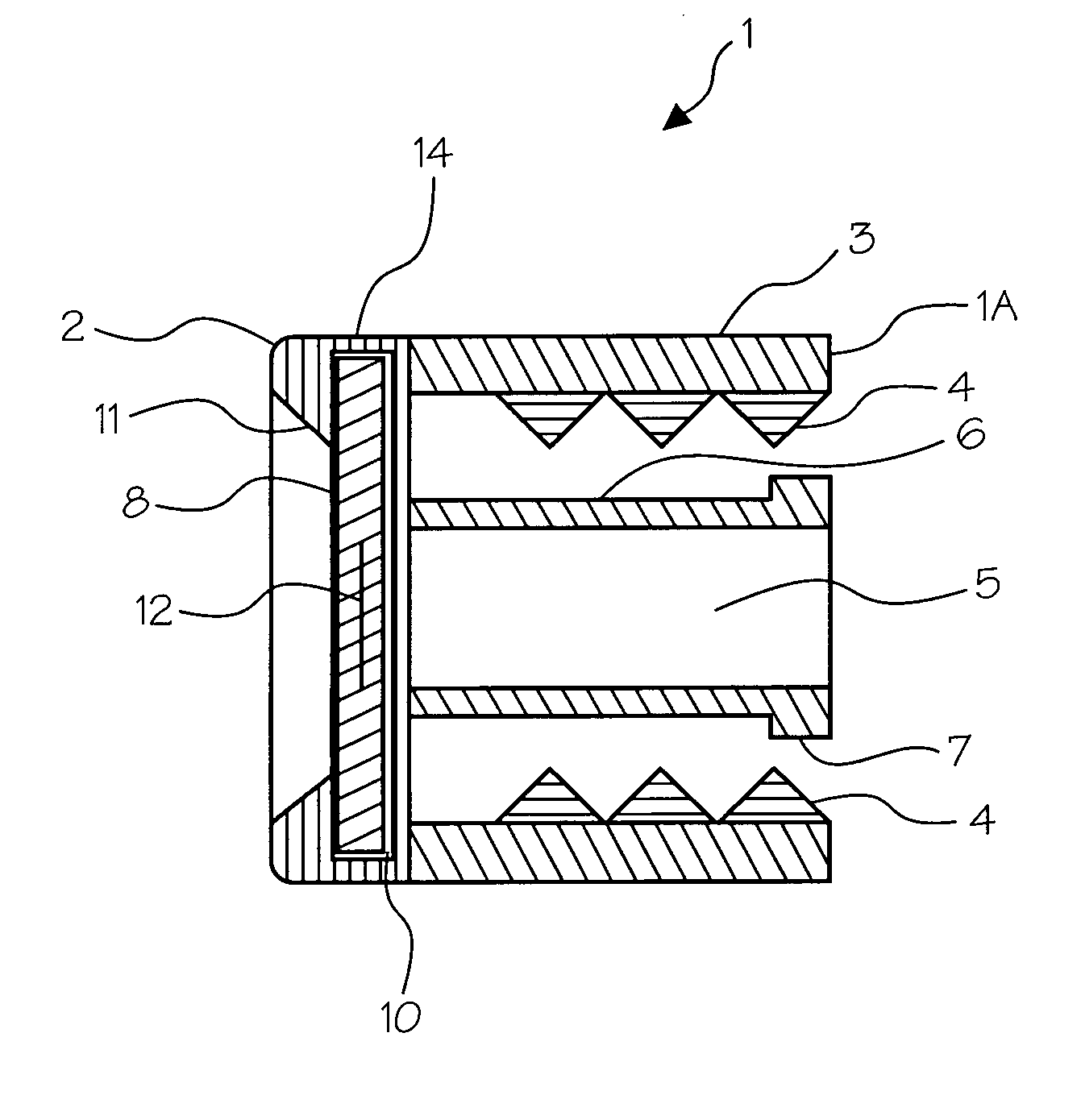
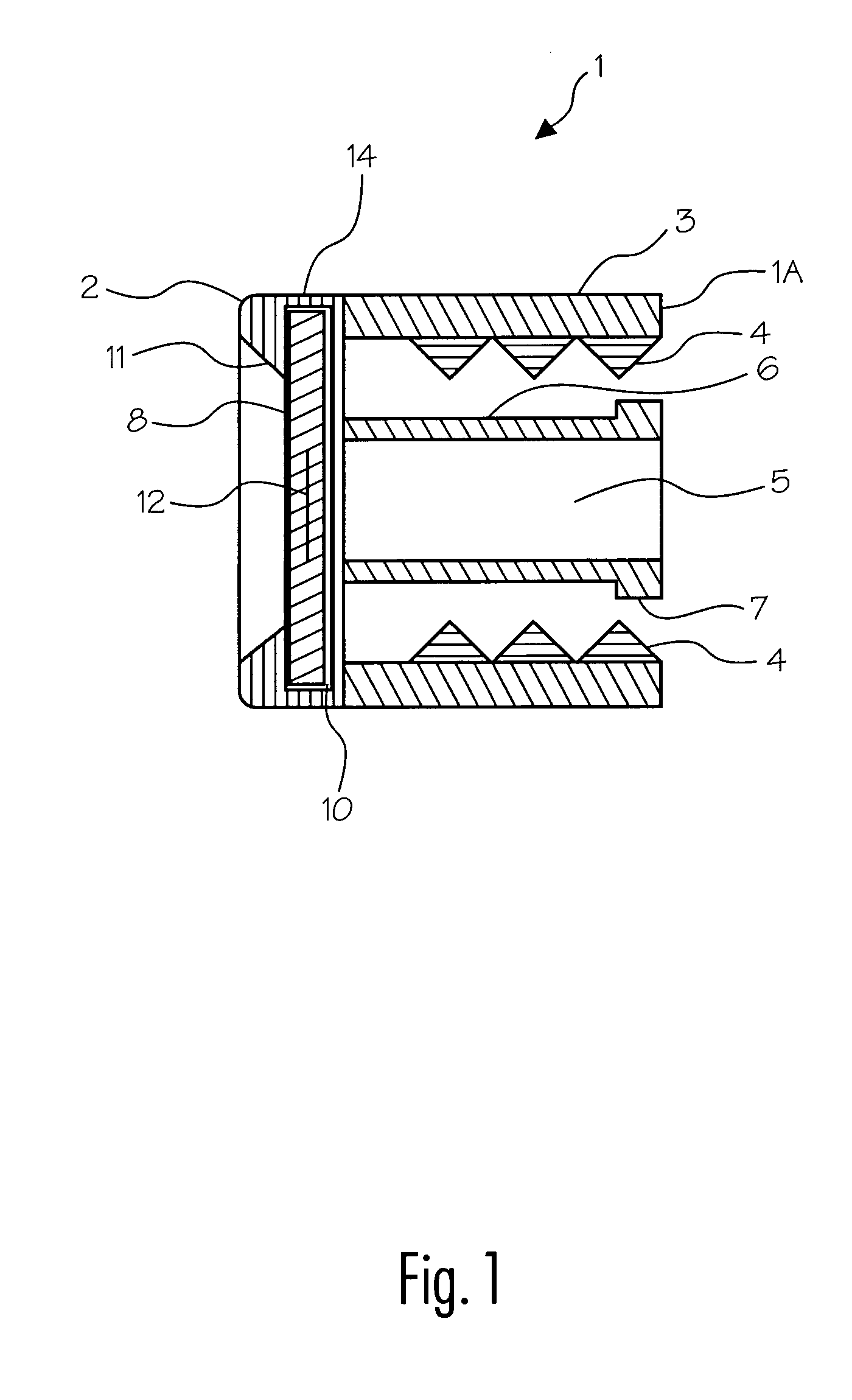
[0023]FIG. 1 is a cross-sectional, side view of a cap 1 showing a central post 6 and an enclosed thread 4 to threadibly engage a matching thread of body 30 of the vascular sheath 100 (see FIG. 6). The purpose of cap 1 is to seal sheath 100 and, in particular, to compress primary seal (or O-ring) 20, and any suitable structure may be used for this purpose. In this embodiment cap 1 is generally circular in shape. Cap 20 is preferably comprised of injection molded plastic such as polyethylene, polypropylene or vinyl, but may be of any suitable material and manufact...


PUM


Abstract

Disclosed is a vascular sheath for helping to prevent bleeding during procedures in which devices must be inserted into a blood vessel such as an artery or vein. The vascular sheath includes at least one manually compressible primary seal that has a lumen passing therethrough. A device inserted into the blood vessel first passes through the sheath, and thus through the lumen in the primary seal. By manually adjusting the compression of the primary seal the size of at least part of the lumen is made to substantially conform to the outer surface of the device. The primary seal can thus seal against large and small sized devices to prevent bleeding. It is preferred that a secondary seal also be used and one type of secondary seal is a flexible disk or flap with one or more slits through which the device passes.

Description

RELATED APPLICATIONS [0001] This application claims priority to U.S. Provisional Application Ser. No. 60 / 538,712, filed Jan. 23, 2004, by inventor John C. Opie, which is incorporated herein by reference.FIELD OF THE INVENTION [0002] The present invention relates to medical systems and methods, and more particularly, to a vascular sheath to assist in preventing excessive bleeding during certain medical procedures. BACKGROUND OF THE INVENTION [0003] This invention relates to vascular sheaths (preferably larger diameter sheaths) having an improved hemostatic valve or gasket assembly to assist in preventing excessive bleeding when the sheath is “dormant.”“Dormant” in this context means that the sheath is temporarily transmitting and / or retaining a small diameter secondary device such as a medical guide wire (also referred to herein as a guide wire or wire), or diagnostic catheters for procedures such as serial angiograms. [0004] Vascular sheaths (also referred to herein as a sheath or v...

Claims


Application Information

Patent Timeline
Patent Type & Authority Applications(United States)
IPC IPC(8): A61M5/178A61M39/02A61M39/06A61M39/20
CPCA61M39/06A61M39/20A61M2039/064A61M2039/0633A61M2039/0202
Inventor OPIE, JOHN C.
Owner JS VASCULAR
Why Eureka
Try Eureka