
Pedal with fastening clip for push rod

a technology of fastening clip and push rod, which is applied in the direction of mechanical control devices, controlling members, domestic objects, etc., can solve the problems of reducing the number of parts, reducing the maximum strength of the device, and reducing the variety of parts.

Inactive Publication Date: 2005-11-03
ZF BOGE ELASTMETALL
View PDF2 Cites 4 Cited by
  • Summary
  • Abstract
  • Description
  • Claims
  • Application Information

AI Technical Summary

Benefits of technology

[0007] One basic object of the present invention is to further improve a fastening device of pedal with an insert for connecting to a push rod, especially with a design such that maximum strength of the device is guaranteed, on the one hand, and, on the other hand, the wide variety of parts is reduced.
[0012] Concerning the nature of its material, the pedal is made according to the present invention as a two-component pedal made as a plastic part, which is reinforced with metal. Because of the high stability of such a hybrid design of the pedal, it is possible to directly anchor the fastening clip in the pedal without having to use a shell, which has hitherto been common, as a pedal module. The wide variety of parts of the actuating means is reduced as a result.

Problems solved by technology

Fastening devices especially of the type mentioned last have the drawback that, on the one hand, the lateral snap hooks or the pedal-side hooks corresponding to them become blunt and lose their hooking property or even break off in case of frequent removal of the plastic insert.
On the other hand, the plastic insert does not have the maximum strength that would be desirable even in the installed state at right angles to the axis of the push rod because of its removal opening.
Even buckling of the insert would be possible on the side located opposite the opening under a corresponding (lateral) load, which can lead to an undesirable breaking off of the insert part in the worst case.
The insert part may also be unintentionally twisted and damaged during nonuniform opening of the snap hooks or during nonuniform removal because of the removal opening.

Method used


Image

  • Pedal with fastening clip for push rod
  • Pedal with fastening clip for push rod
  • Pedal with fastening clip for push rod

Examples


Embodiment Construction

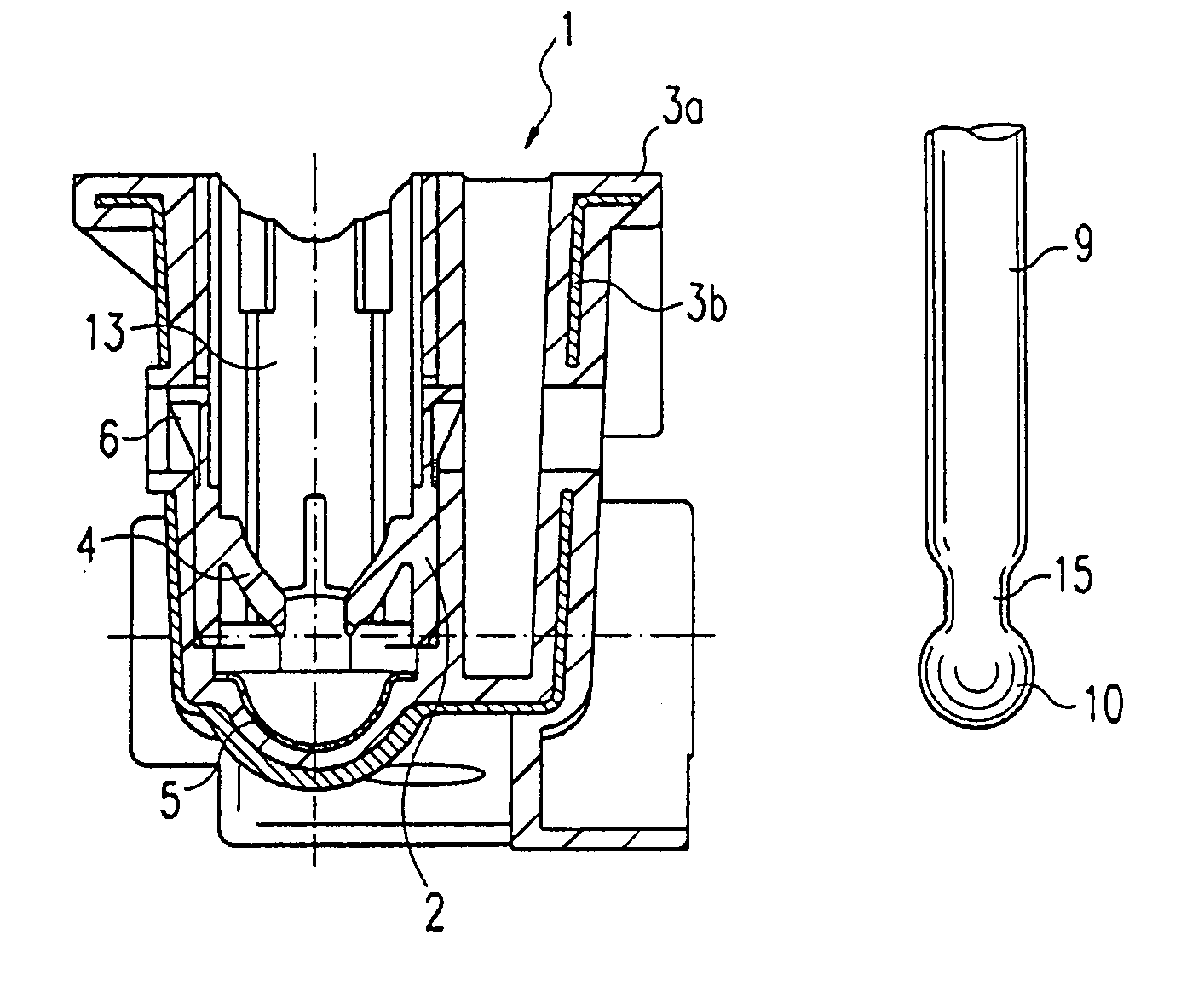
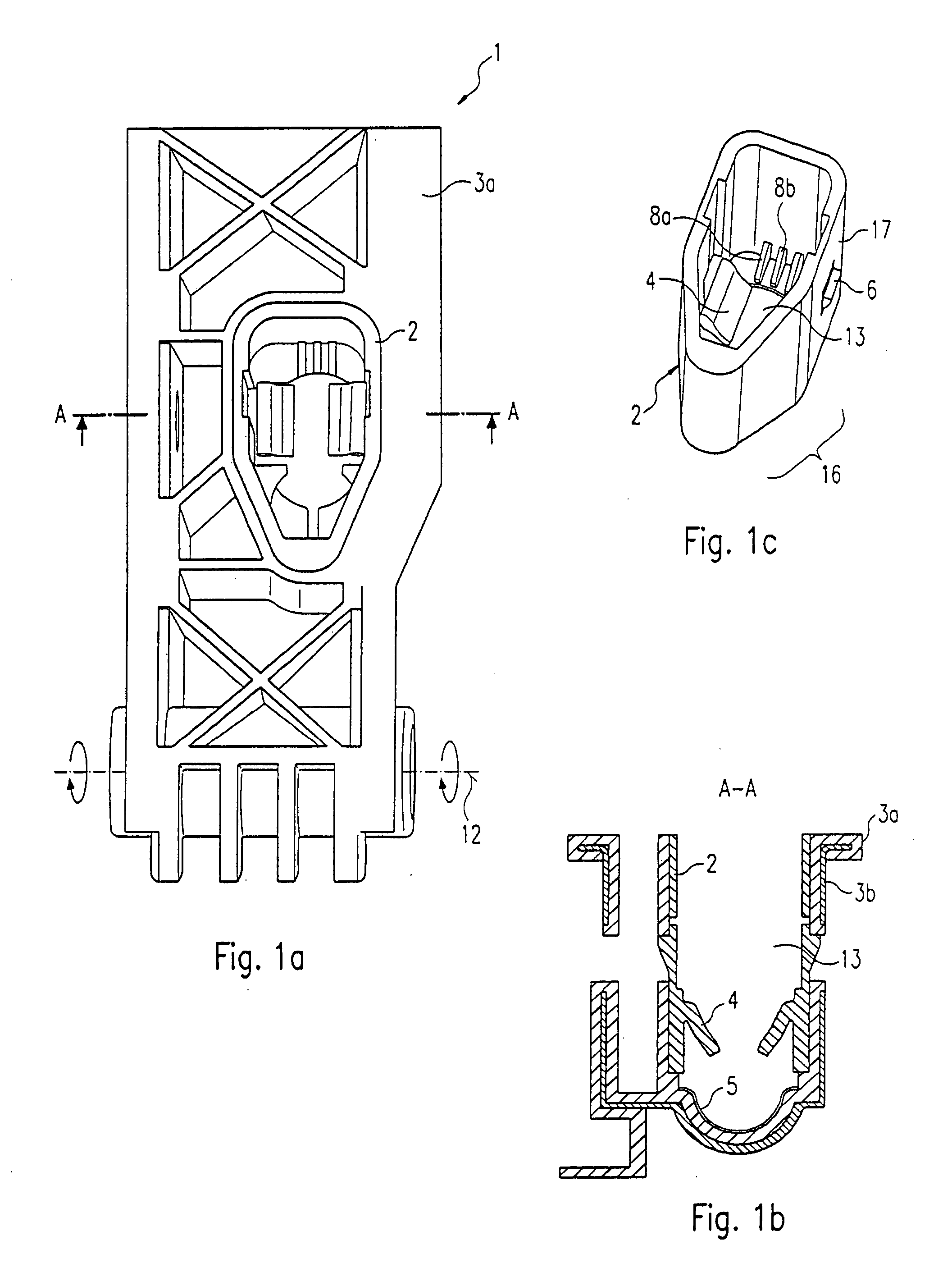
[0029] Referring to the drawings, FIG. 1a shows on the push rod side the hybrid brake pedal 1 according to the present invention with the fastening clip 2 according to the present invention snapped in and without the push rod. The pedal is mounted rotatably about an axis 12 and can be pivoted by the driver. In this way the pivoting movement of the pedal is converted into an axial movement of the push rod with the push rod installed in the fastening clip according to the present invention. The brake servo unit cylinder in the front area of the vehicle is thus mechanically acted on. The fastening clip 2 according to the present invention is snapped approximately at half-height of the pedal 1 into the plastic section 3a (see FIG. 5a: Section A-A). The designation “hybrid” stems from the fact that the plastic section 3a proper of the brake pedal is reinforced with a metal structure 3b, i.e., the pedal consists of two different material components. The metal structure 3b comprises sheet ...


PUM


Abstract

A snap connection is provided between a push rod, e.g., of brakes, to an actuating means, e.g., a brake pedal. A fastening clip (2) is detachably fastened to the pedal. The push rod includes a spherical end (10) which can be held in an articulated manner by the fastening clip (2) for transmitting actuating forces. The interior of the fastening clip has two elastically deformable locking lips (4) acting as barbs, which fix the spherical end of the push rod (10) in the pedal (1) after the insertion of the push rod (10) into the fastening clip (2). The fastening clip (2) is preferably a plastic part with essentially closed sides, which are closed off on the pedal side by a front surface with an opening for the spherical end of the push rod. The opening has an insertion area (13) for inserting the spherical end of the push rod (10) and a removal area (14) for removing the push rod (9).

Description

CROSS REFERENCE TO RELATED APPLICATION [0001] This is a continuation of, and claims the benefit (35 U.S.C. §120 and 365(c)) of, copending International Application PCT / DE2004 / 001311 of 23 Jun. 2004, which designated inter alia the United States and which claims the priority of German Application 103 28 542.3 of 24 Jun. 2003. The entire contents of each application is hereby incorporated by reference in its entirety.FIELD OF THE INVENTION [0002] The present invention pertains to a fastening device in a motor vehicle. The present invention pertains, in particular, to a snap connection with which a push rod, e.g., of brake devices, is fastened to an actuating means, e.g., a brake pedal. BACKGROUND OF THE INVENTION [0003] It is often necessary in the construction of vehicles to movably couple functional elements in the front area of the vehicle (brake servo unit cylinder, clutch, throttle flap, etc.) with the corresponding actuating means in the passenger compartment (brake pedal, clutc...

Claims


Application Information

Patent Timeline
Patent Type & Authority Applications(United States)
IPC IPC(8): B60T7/06B60T11/18
CPCB60T7/06Y10T74/20528B60T11/18
Inventor BURGSTALER, ANDREEDUTZ, JANMEYER, WOLFGANGPAPKE, SIMONE
Owner ZF BOGE ELASTMETALL
Learn More