
Apparatus for melt-spinning filaments in a yarn forming operation

a technology of yarn forming and filaments, which is applied in the direction of dough shaping, manufacturing tools, spinnerette packs, etc., can solve the problems of loss of production, achieve the effect of high sealing action, maximum deformation, and maximum strength of the housing

Inactive Publication Date: 2006-01-19
SAURER GMBH & CO KG
View PDF10 Cites 0 Cited by
  • Summary
  • Abstract
  • Description
  • Claims
  • Application Information

AI Technical Summary

Benefits of technology

[0012] An additional advantage of the invention is given by the fact that the level of the pressure force for self-sealing securing in place is proportional to the melt pressure. Thus, the connection of the spinneret to the nozzle holder itself remains pressure tight even at the highest melt pressures.
[0013] In the case of a particularly advantageous configuration of the invention, the spinneret and the nozzle holder are connected to one another by a securing means which produces a securing force. Therein the securing force produced by the securing means and the pressure force produced by the deformation of the housing have the same direction. Thus, the spinneret can be held in the nozzle holder even with relatively low securing forces or loosened from the nozzle holder with relatively low de-securing forces.
[0014] In order, in the case of pre-mounted spinnerets, not to get an adverse effect between the individual parts, such as, for example, the nozzle plate and the housing, the embodiment of the invention is particularly preferred in which the annular wall of the housing has a form and a material which leads to a directionally related deformation under pressure. In particular, a predefined deformation under melt pressure can be achieved by a particular shaping of the housing. Thus, maximum pressure forces can be produced at those sealing points that are to be sealed.
[0015] The sealing joints formed between the melt outlet of the nozzle holder and the melt inlet of the spinneret can even be advantageously sealed by the wall of the housing in the area of the melt outlet in such a manner that it is deformable under pressure. The deformation produced by the pressure force thus acts directly on the sealing face formed between the spinneret and the nozzle holder.
[0016] To ensure the necessary strength of the housing, the wall of the housing is preferably formed as a thin-walled spherical cap. With this, a maximum deformability is achieved with maximum strength of the housing. In principle however, any shaping of the housing is possible which causes the desired elastic deformation.
[0017] The embodiment of the invention in which a sealing ring is disposed between the melt outlet of the nozzle holder and the melt inlet of the housing is distinguished by the fact that even the slightest deformations of the housing lead to a high sealing action.

Problems solved by technology

The removal of the spinnerets is laborious and causes unavoidable downtimes which lead to a loss of production.
However, apparatus of this type have the basic disadvantage that during operation a deformation of the sealing ring occurs so that a securing in place between the sealing ring and the nozzle holder hinders the loosening of the spinneret.
However, the movable arrangement of the individual parts of the spinneret has the great disadvantage that the spinneret is not held in the nozzle holder in such a manner that it can be removed as a structural unit.

Method used


Image

  • Apparatus for melt-spinning filaments in a yarn forming operation
  • Apparatus for melt-spinning filaments in a yarn forming operation
  • Apparatus for melt-spinning filaments in a yarn forming operation

Examples


Embodiment Construction

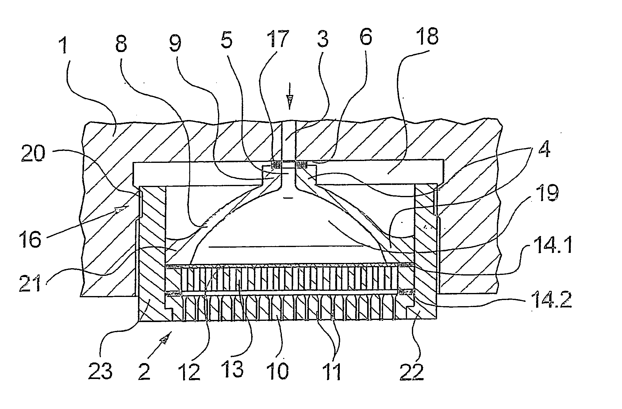
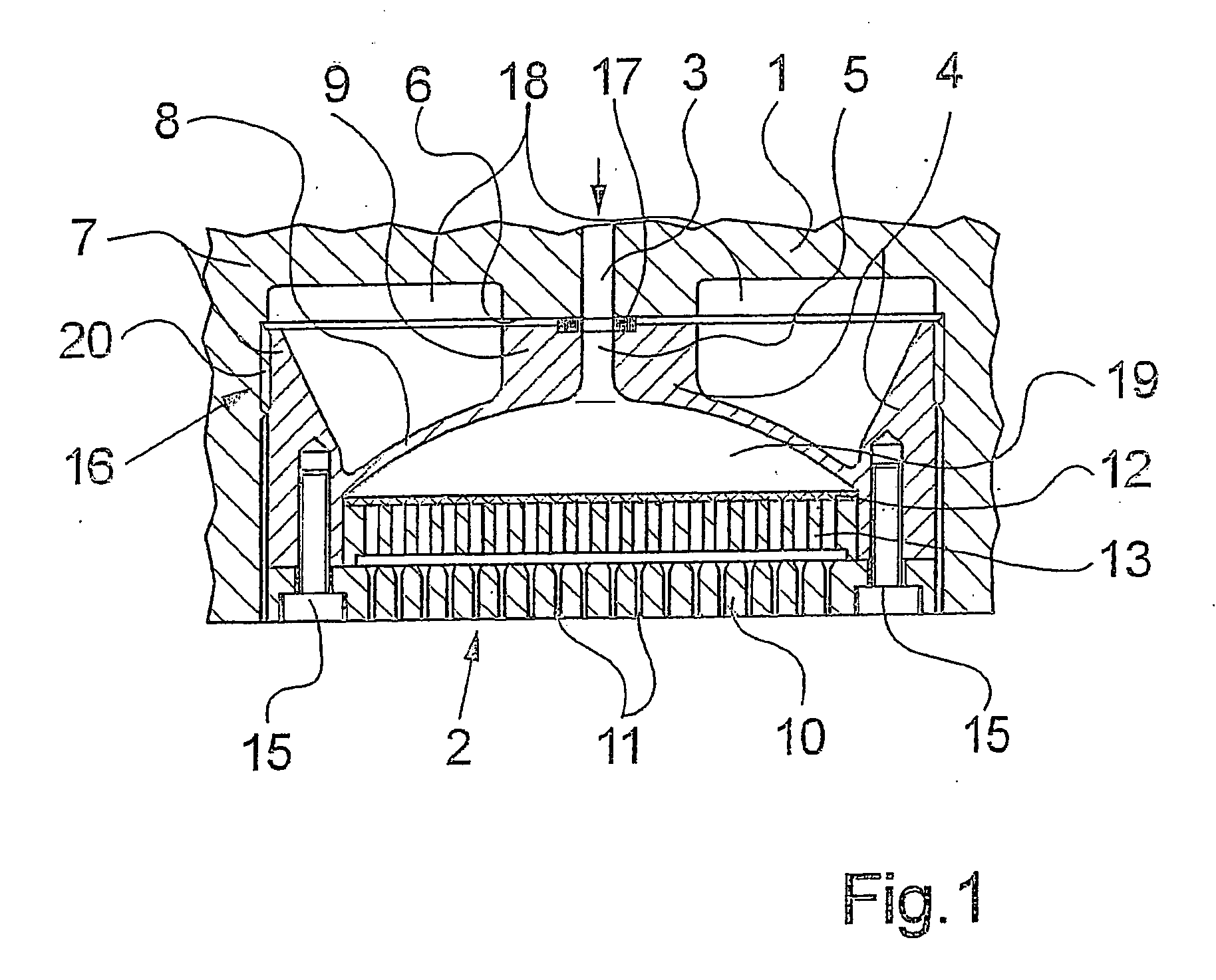
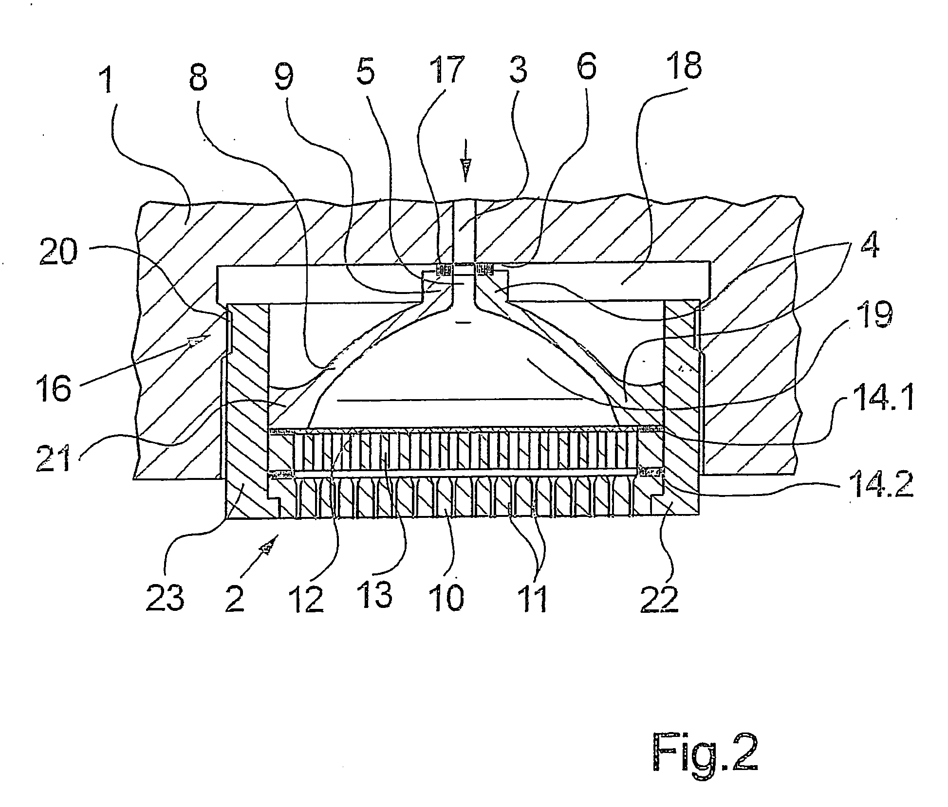
[0023] In FIG. 1 a cross-section of a first embodiment of the apparatus according to the invention is shown in schematic form. The apparatus comprises a nozzle holder 1 which comprises on an underside a downwardly opening receptacle 18 which is configured to receive a spinneret 2. The nozzle holder 1 usually comprises on the underside several such receptacles (not represented here) to receive several spinnerets. For each receptacle 18 the nozzle holder 1 contains a melt outlet 3, via which a polymer melt is fed to the spinneret 2. The nozzle holder 1, which is also designated as a so-called spinning beam, contains additional melt feeding components such as lines and spinning pumps, which are not represented here.

[0024] The nozzle holder 1 is formed in such a manner that it can be heated. Thus, the melt feeding components received by the nozzle holder 1 can be kept at a specified temperature at their walls or the walls of the nozzle holder by a heat transfer medium or by an electric...


PUM

PropertyMeasurementUnit
melt pressuresaaaaaaaaaa
pressureaaaaaaaaaa
pressure forceaaaaaaaaaa

Abstract

An apparatus for melt spinning a plurality of strand-like filaments through a spinneret, which is mounted within a downwardly open receptacle in a nozzle holder. The spinneret includes a housing which is deformed by the entry of the pressurized polymeric melt into an internal diffuser chamber, so as to press the spinneret against the inner wall of the receptacle and thereby seal the melt inlet of the spinneret against the melt outlet in the receptacle. Thus the high pressure forces required for sealing only arise and are active during the operational state, and the spinneret can be otherwise held in the nozzle holder under a minimal securing force which permits the spinneret to be easily loosened and removed for periodic maintenance.

Description

CROSS REFERENCE TO RELATED APPLICATION [0001] The present application is a continuation of international application PCT / EP2004 / 003212, filed 26 March, 2004, and which designates the U.S. The disclosure of the referenced application is incorporated herein by reference.BACKGROUND OF THE INVENTION [0002] The present invention relates to a apparatus for the melt-spinning of a plurality of strand-like filaments in a yarn forming operation. [0003] For the melt-spinning of synthetic fibers, a melted polymer material is extruded to form a plurality of strand-like filaments. For this, it is necessary that the polymer melt be pressed through nozzle holes. The extrusion, which is also called spinning out, is done by a spinneret which comprises on its underside a plurality of nozzle holes. In practice, several spinnerets of this type are used simultaneously alongside one another in order to extrude several fiber bundles in parallel to one another. For this, the spinnerets are held in a nozzle ...

Claims


Application Information

Patent Timeline
Patent Type & Authority Applications(United States)
IPC IPC(8): B29C47/00D01D4/08
CPCD01D4/08
Inventor REUTTER, TILMANVOLLMERS, CHRISTIAN
Owner SAURER GMBH & CO KG
Learn More