
Presentation device and display method

a technology of a display device and a display method, which is applied in the field of presentation devices, can solve the problems of difficulty in specifically determining the location of the area that is actually magnified after the zooming operation in the image currently displayed on the display devi

Inactive Publication Date: 2005-11-03
ELMO CO LTD
View PDF7 Cites 38 Cited by
  • Summary
  • Abstract
  • Description
  • Claims
  • Application Information

AI Technical Summary

Benefits of technology

[0006] In view of the foregoing, an object of the present invention is to provide a presentation device which would allow the location of the magnified area to be readily indicated while previewed.
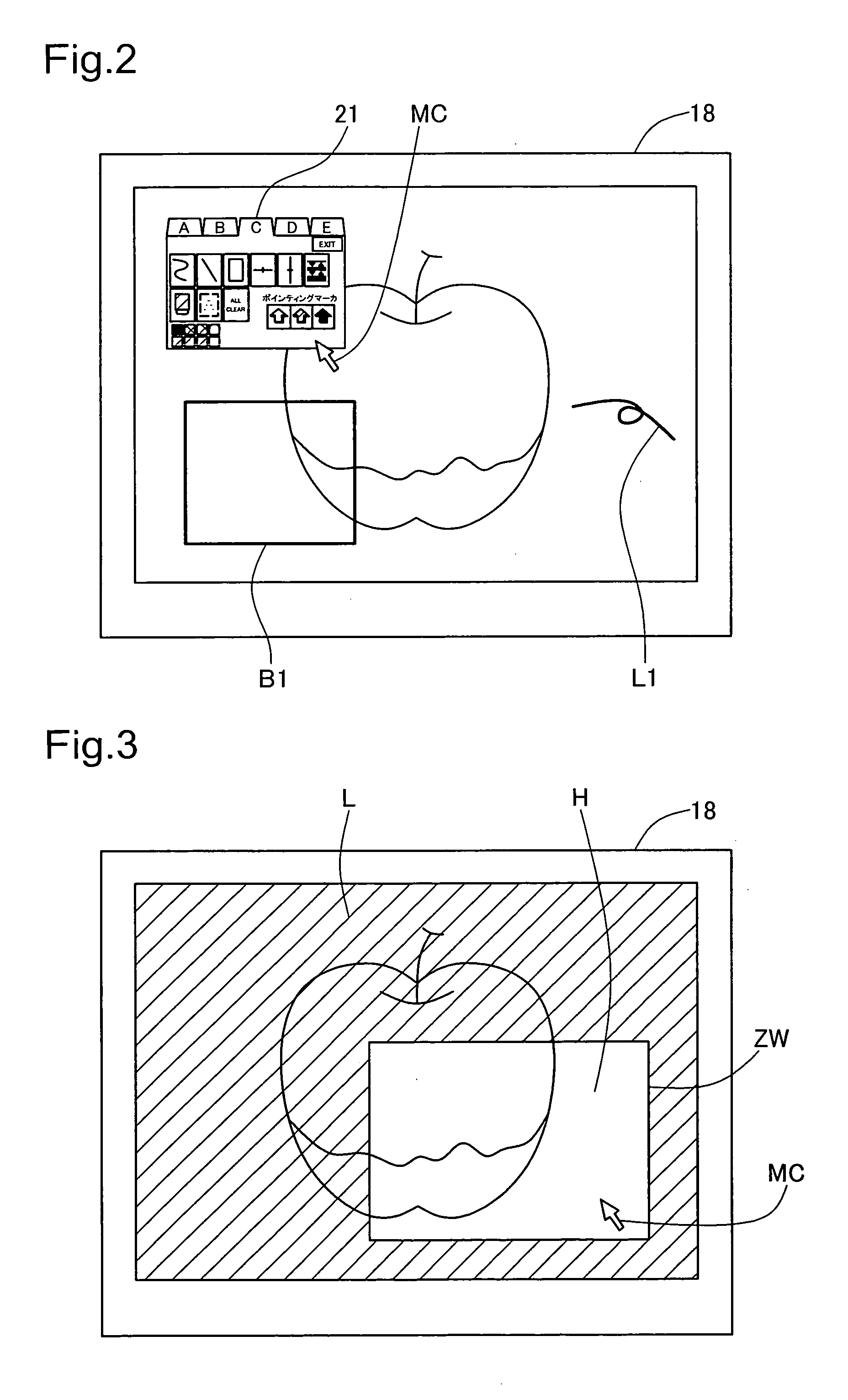
[0008] The presentation device of the invention allows a window that moves according to the moving operation of a pointing device to be displayed in the image, and magnifies the area shown in the window. The user can thus readily indicate the location of the magnified area while viewing it. Various input devices such as a mouse, tablet, digitizer, tracking ball, joystick, or remote control with arrow keys can be used as the pointing device.
[0010] In this arrangement, the location in the image indicated by the cursor will not change before or after the image is magnified. The user can thus operate the pointing device without becoming disoriented after the image has been magnified. This arrangement is also more convenient to use because the area that is to be magnified can be indicated by indicating the cursor position in addition to the window.
[0011] The window display unit may display the window by increasing the brightness of the part of the area in the image. The window display unit may also display the window by lowering the brightness of the parts other than the part of the area in the image. This allows the part that will be magnified to be clearly distinguished from the other parts, making it easier to indicate the magnified part.
[0014] The camera in the presentation device having the aforementioned structure may comprise a zoom mechanism capable of optically magnifying and projecting the materials, wherein the magnifying display unit controls the zoom mechanism to magnify and project the area shown in the window, and displays the magnified projected image. This embodiment allows the image to be optically magnified, and can thus improve the quality of the magnified image.

Problems solved by technology

However, even though the zoom function in conventional presentation devices make it possible to learn beforehand a point of reference for magnified display that will result in the position of the mouse cursor or the central portion on the display device, it is difficult to specifically ascertain where the area that is actually magnified after the zooming operation is located in the image currently displayed on the display device.

Method used


Image

  • Presentation device and display method
  • Presentation device and display method
  • Presentation device and display method

Examples


Embodiment Construction

[0022] Embodiments of the invention are illustrated in the following order based on examples. [0023] A. Schematic Structure of Material Presentation Device [0024] B. Internal Structure of Material Presentation Device [0025] C. Magnified Display Process

C. Other Embodiments

[0026] A. Schematic Structure of Material Presentation Device:

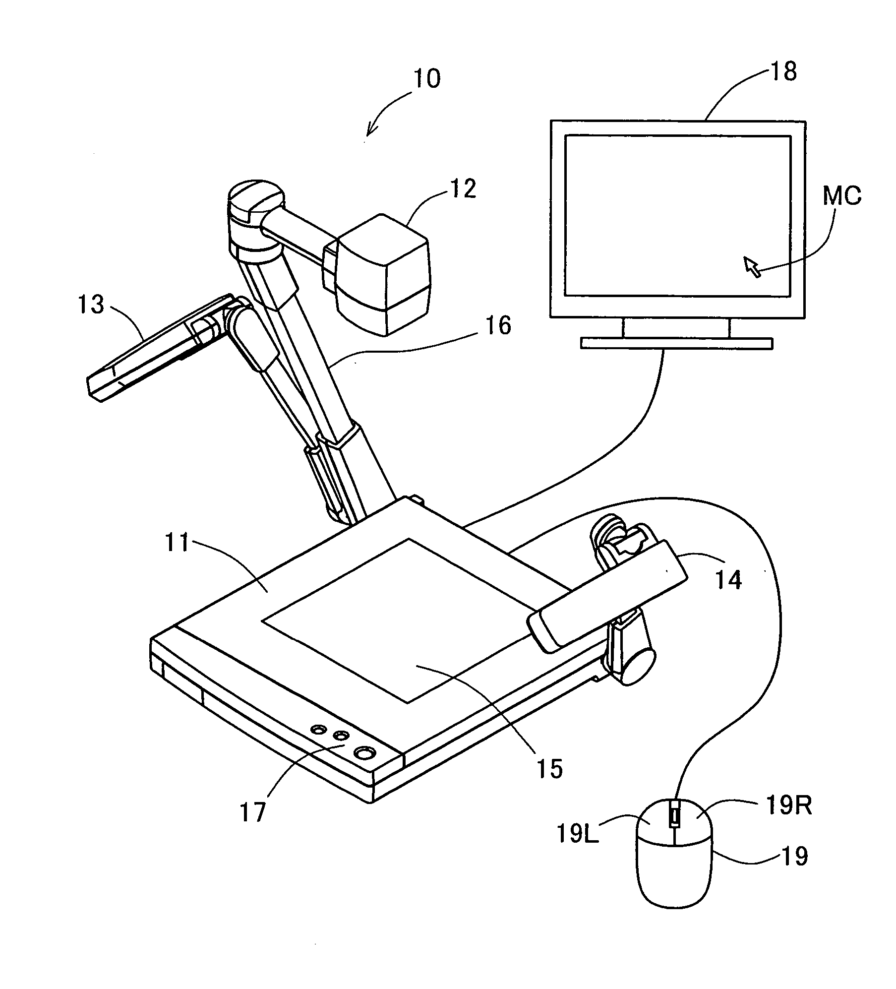
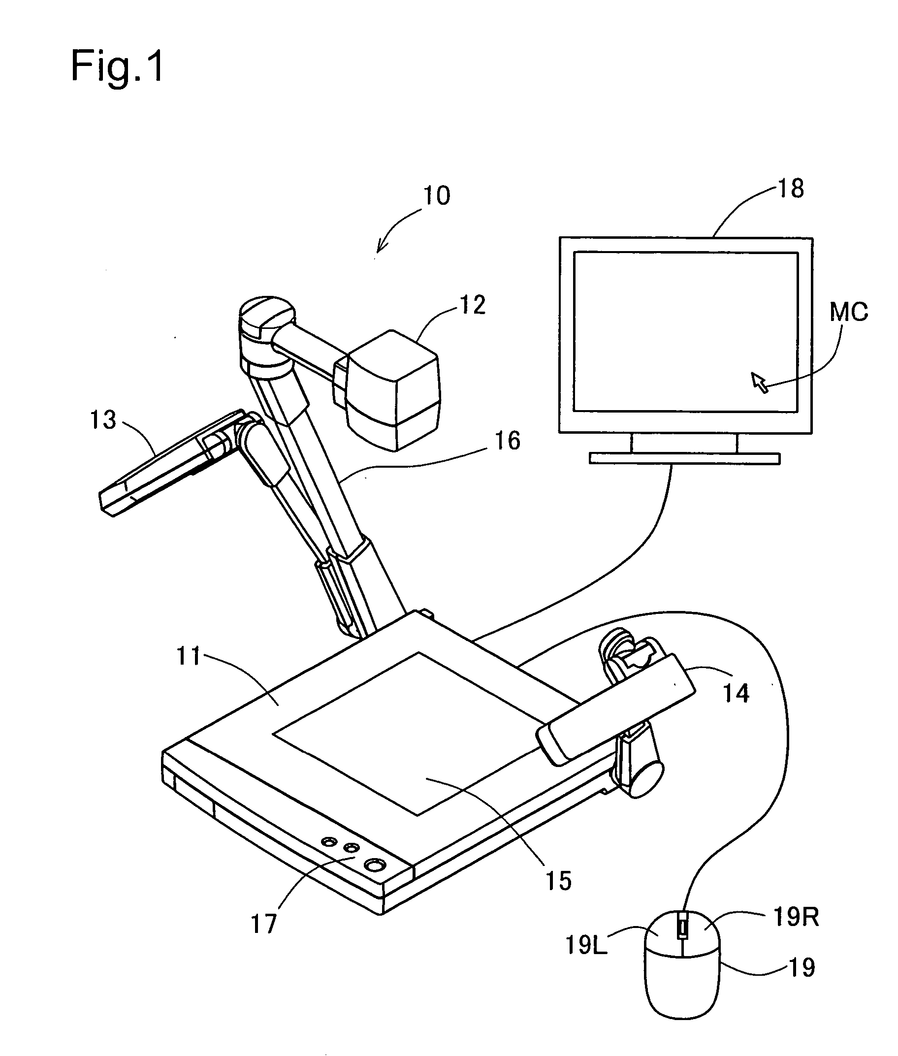
[0027]FIG. 1 illustrates the schematic structure of the material presentation device 10 as an example of the invention. The material presentation device 10 is made of a material holding stand 11, which accounts for most of the bottom, a camera head 12 facing the stand, and left and right lights 13 and 14, etc., illuminating the material holding stand 11 from above. The lights 13 and 14 are rotatably connected to the left and right rear ends of the material holding stand 11, and are used as needed during the projection of the materials on the material holding stand 11. The upper surface of the material holding stand 11 is made of a light-transmitting ma...


PUM


Abstract

Upon certain operations by a user, the presentation device displays a zoom window ZW in an image. The user moves the zoom window ZW by moving a mouse 19, so as to indicate a desired area in the image. When the desired area is indicated by the user, the presentation device magnifies and displays the area in the zoom window ZW. The area H in the zoom window is displayed with relatively higher brightness than other areas. As a result, the presentation device of the invention allows the location of the magnified area to be readily indicated while previewed.

Description

BACKGROUND OF THE INVENTION [0001] 1. Field of the Invention [0002] The invention relates to a presentation device for producing an image by projecting materials such as a document and samples with a camera, and displaying the images on an external display device. [0003] 2. Description of the Related Art [0004] The presentation devices are used in the field or the like to give presentations. Most have a zoom function allowing materials projected by a camera to be magnified and displayed on a display device (such as Japanese Unexamined Patent Application 2002-281467A). In conventional zoom functions of this type, the magnified display is based on the position of a mouse cursor displayed on the display device or the center portion on the display device. [0005] However, even though the zoom function in conventional presentation devices make it possible to learn beforehand a point of reference for magnified display that will result in the position of the mouse cursor or the central port...

Claims


Application Information

Patent Timeline
Patent Type & Authority Applications(United States)
IPC IPC(8): G06F3/14H04N5/222G09F9/00G09G5/00
CPCG09G2320/0686H04N1/00236H04N1/00424H04N1/00432H04N1/0044H04N1/00469H04N2201/0436H04N1/195H04N1/19594H04N5/23216H04N5/23296H04N2201/0081H04N1/10H04N23/62H04N23/69
Inventor HASHIMOTO, SUSUMUKOJIMA, MIKIHIRO
Owner ELMO CO LTD
Learn More