Transflective liquid crystal display with bent electrodes

a liquid crystal display and electrode technology, applied in non-linear optics, instruments, optics, etc., can solve the problem that the liquid crystal molecules adjacent to the substrate cannot be perpendicular to the substrate, and achieve the effect of improving display performan

Inactive Publication Date: 2005-11-03
INNOLUX CORP
View PDF9 Cites 33 Cited by
  • Summary
  • Abstract
  • Description
  • Claims
  • Application Information

AI Technical Summary

Benefits of technology

[0012] Because the pixel electrodes and common electrodes are bent, when a voltage is applied on the electrodes, an electric field in two directions is generated. Liquid crystal molecules of the liquid crystal layer are oriented in two directions in accordance with the electric field. Therefore, any color shift observed by viewing the transflective liquid crystal display from different directions is reduced, and a better display performance is attained.

Problems solved by technology

However, the liquid crystal molecules adjacent to the substrate cannot be oriented perpendicular to the substrate when an electric field is applied.

Method used


Image

  • Transflective liquid crystal display with bent electrodes
  • Transflective liquid crystal display with bent electrodes
  • Transflective liquid crystal display with bent electrodes

Examples


Embodiment Construction

[0023] Reference will now be made to the drawings to describe the preferred embodiments in detail.

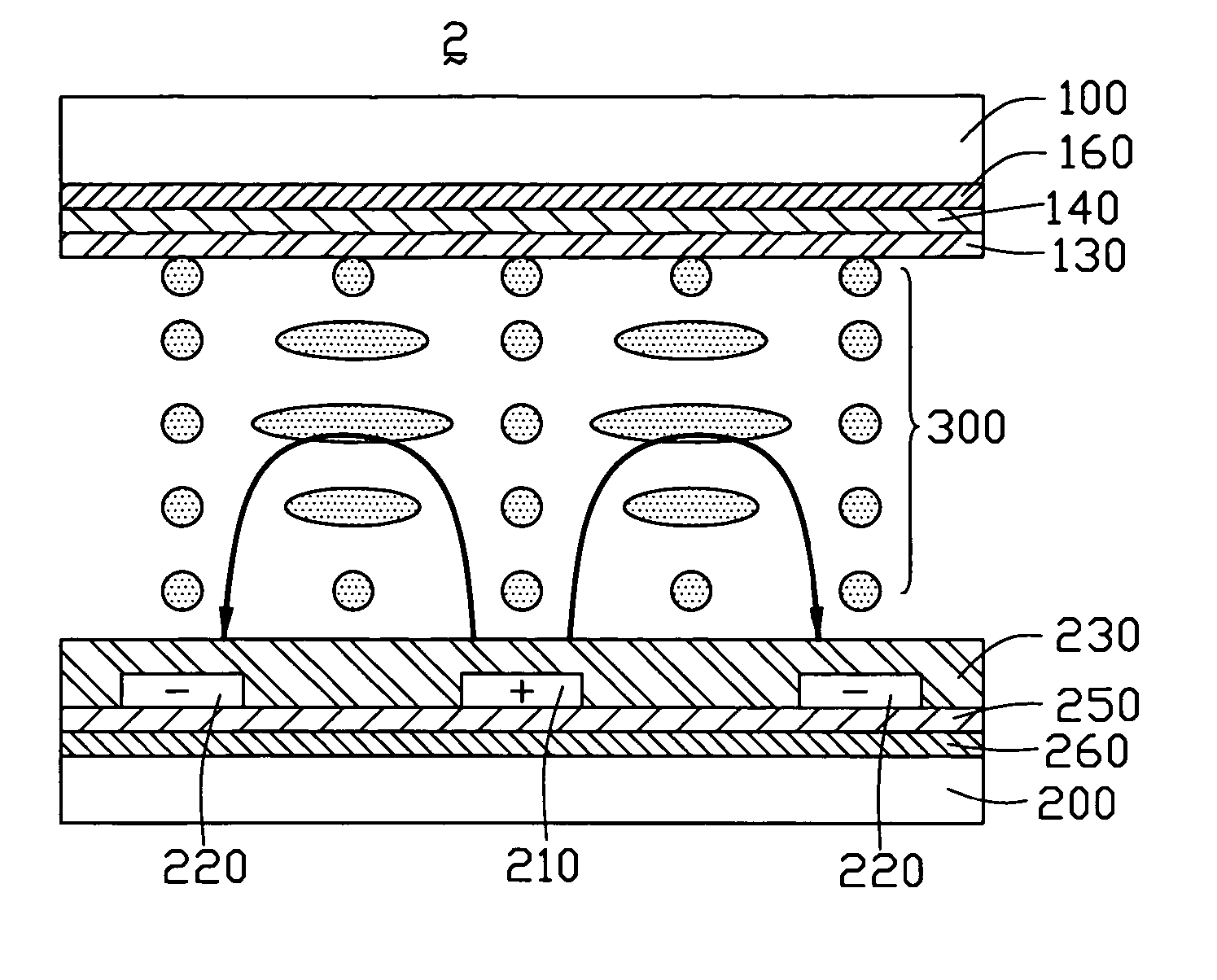
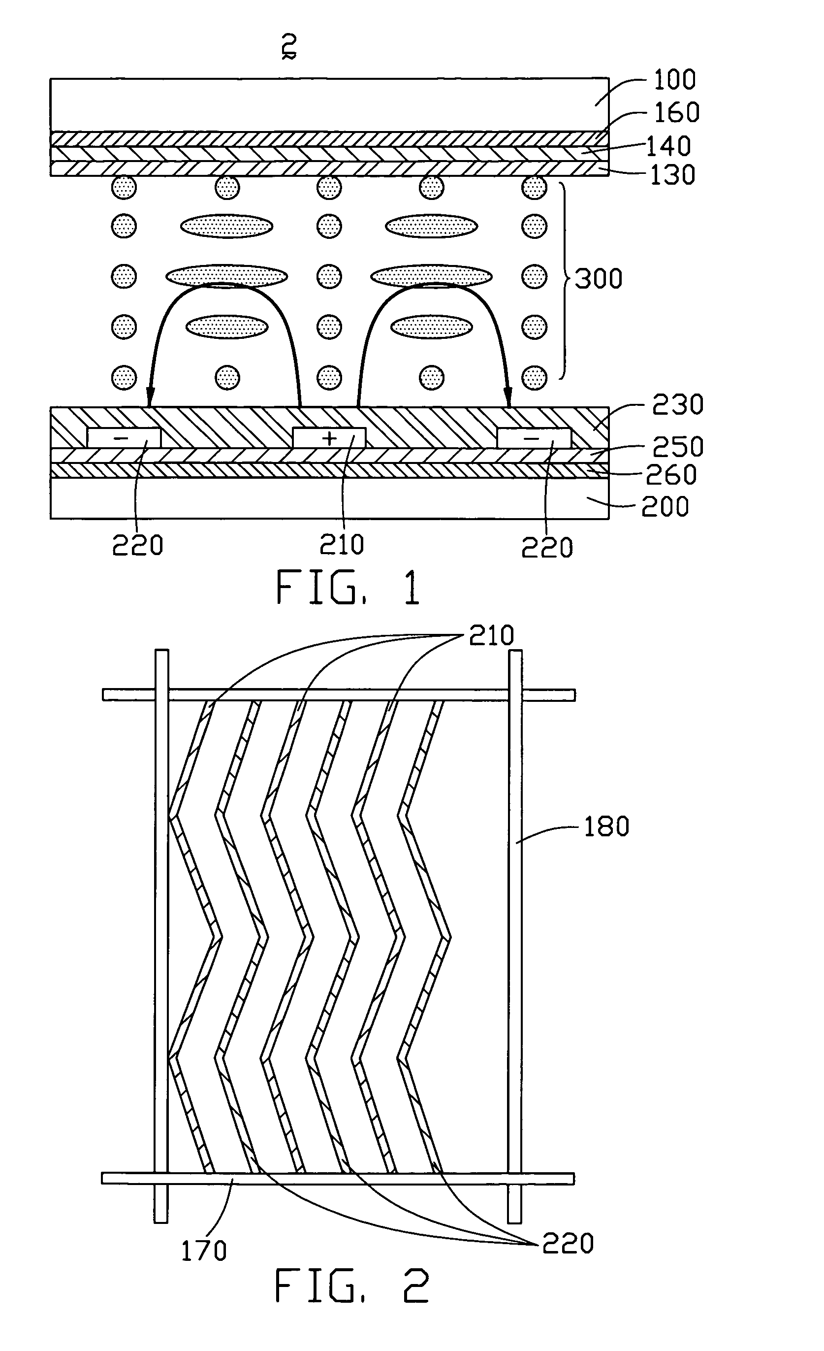
[0024]FIG. 1 is a schematic, cross-sectional view of part of a transflective liquid crystal display according to a first preferred embodiment. The transflective liquid crystal display 2 includes an upper substrate 100, and a lower substrate 200 opposite to the upper substrate 100. A liquid crystal layer 300 is sandwiched between the substrates 100, 200. An upper polarizer 160, a color filter 140 and an upper alignment film 130 are formed in sequence at an inner side of the upper substrate 100. A lower polarizer 260, a transflective layer 250 and a lower alignment 230 are formed in sequence at an inner side of the lower substrate 200. A plurality of pixel electrodes 210 and common electrodes 220 is formed between the transflective layer 250 and the lower alignment 230.

[0025] The pixel electrodes 210 and the common electrodes 220 are located on the transflective layer 250. The transflec...


PUM

PropertyMeasurementUnit
shapeaaaaaaaaaa
transparentaaaaaaaaaa
electric fieldaaaaaaaaaa

Abstract

A transflective liquid crystal display (2) includes a transparent upper substrate (100), a lower substrate (200) opposite to the upper substrate, a liquid crystal layer (300) sandwiched between the two substrates, gate lines (170) and data lines (180) defining pixel units arranged in a matrix, pixel electrodes (210) and common electrodes (220) associated with one of the substrates to each pixel unit of one of the substrates, a transflective layer (250) formed at one side of one of the substrates. The pixel electrodes and the common electrodes have the same bent form, are disposed alternately, and are substantially parallel to each other. When a voltage is applied on the electrodes, an electric field in two directions is generated. Liquid crystal molecules of the liquid crystal layer are oriented in two directions in accordance with the electric field. Therefore, color shift is reduced.

Description

BACKGROUND [0001] 1. Field of the Invention [0002] The present invention relates to a liquid crystal display, and particularly to a transflective type IPS LCD (in-plane switching liquid crystal display). [0003] 2. General Background [0004] In a liquid crystal display, a pair of transparent electrodes is respectively formed on each of two substrates, and is used for driving a liquid crystal layer between the substrates. In a typical such device, a displaying means known as a TN (twisted nematic) display is adopted. That is, the liquid crystal display operates by being supplied with an electric field having a direction orthogonal to inner the surfaces of the substrates. [0005] However, the liquid crystal molecules adjacent to the substrate cannot be oriented perpendicular to the substrate when an electric field is applied. Further, the tilt angles of the liquid crystal molecules tend to differ. When a user observes the display from different directions, different display performances ...

Claims


Application Information

Patent Timeline
Patent Type & Authority Applications(United States)
IPC IPC(8): G02F1/1335G02F1/1343
CPCG02F1/134363G02F1/133555
Inventor YANG, CHIU-LIENPANG, JIA-PANGCHEN, CHUEH-JU
Owner INNOLUX CORP
Why Eureka
Try Eureka