Wall roll-up screen

Inactive Publication Date: 2005-11-03
CHOI HAE YONG
View PDF9 Cites 9 Cited by
  • Summary
  • Abstract
  • Description
  • Claims
  • Application Information

AI Technical Summary

Benefits of technology

[0003] The present invention has been made in view of the above problems, and it is an object of the present invention to provide a wall roll-up screen among portable screens f

Problems solved by technology

And, when a user wishes to carry the screen, the user has to tie it with the string 11, which is tr

Method used


Image

  • Wall roll-up screen
  • Wall roll-up screen
  • Wall roll-up screen

Examples


Example

[0017] The present invention will now be described more fully hereinafter with reference to the accompanying drawings, in which preferred embodiments of the invention are shown. This invention may, however, be embodied in different forms and should not be construed as limited to the embodiments set fourth herein. Rather, these embodiments are provided so that this disclosure will be thorough and complete, and will fully convey the scope of the invention to those skilled in the art. In the drawings, like numbers refer to like elements throughout the specification.

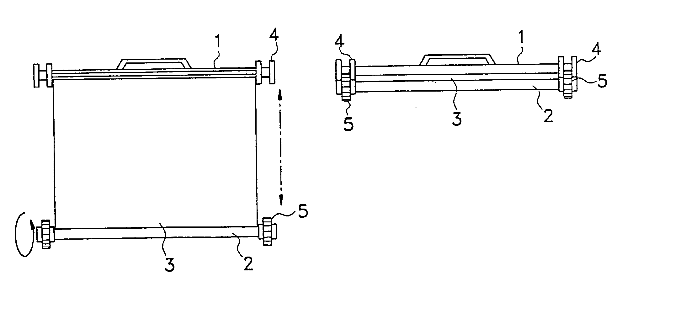
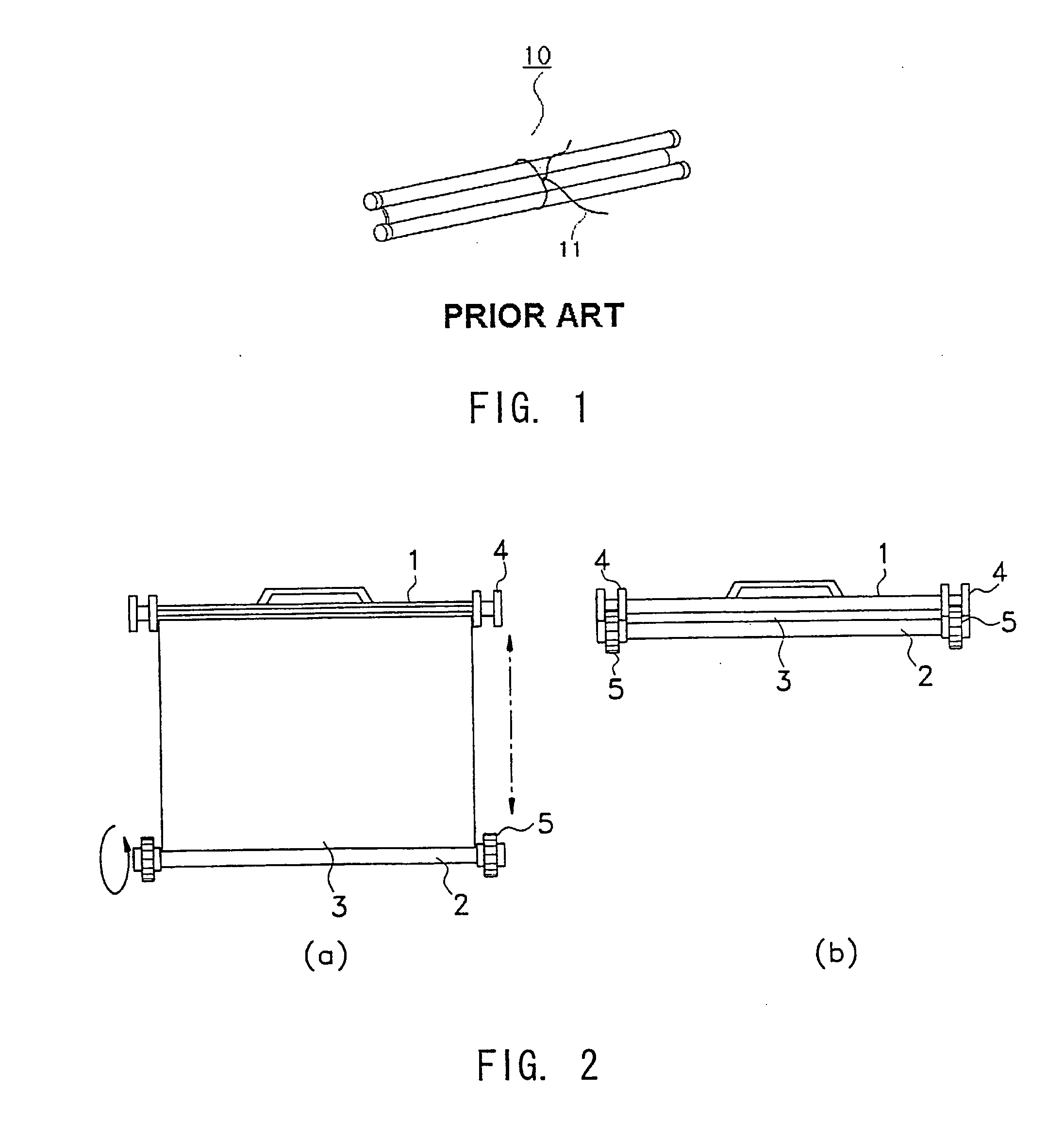
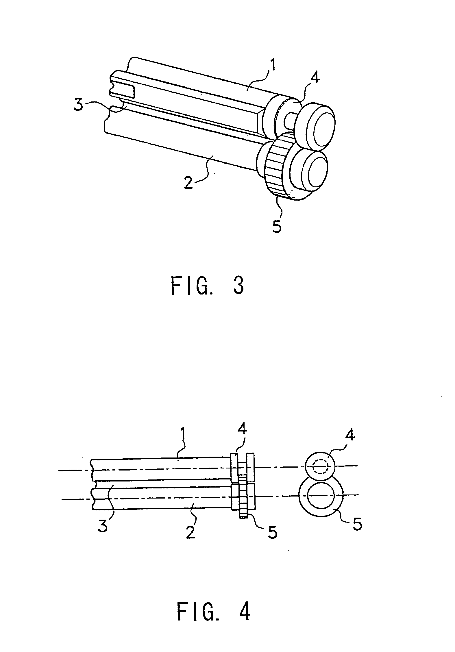
[0018] The screen of the present invention can be used and portable with ease by attaching a magnet assembly to both sides of a lower rod of the screen. When the screen is used, the lower rod 2 is separated from an upper rod 1 of the screen 3 to be extended. And, when the screen is carried, the screen 3 is rolled up and the upper and lower rods 1 and 2 are attached each other so that it is convenient to carry the screen wit...


PUM


Abstract

The device relates to a wall roll-up screen of which the upper and the lower are attached with the upper short rod and the lower short rod, respectively, wherein the screen is constituted to be rolled up when not in use and to be unrolled when used, by the lower short rod; and the left and the right end of the upper short rod are mounted with steel structure of groove shaped ringscapable of coupling magnets and the left and the right end of the lower short rod are mounted with magnets to allow them to be coupled with the groove shaped rings of the left end and the right end of the upper short rod, upon rolling up the screen by the lower short rod and, if necessary, separating the magnets from the groove shape rings, thereby to obtain good portability and mobility of the screen, to prevent the screen from being twisted from side to side upon fixing the screen, and to improve aesthetic value of product.

Description

TECHNICAL FIELD [0001] The present invention relates to a track type wall roll-up screen among portable screens for projection, and more particularly, to a wall roll-up screen wherein the screen can be used and portable with ease by attaching a magnet assembly to both sides of a lower rod of the screen. BACKGROUND ART [0002] In a conventional wall roll-up screen as shown in FIG. 1, it is necessary to roll up the screen 10 around a lower rod like a scroll and to tie the screen with string 11 so as to reserve it, and to untie the string 11 to use the screen 10. And, when a user wishes to carry the screen, the user has to tie it with the string 11, which is troublesome. Especially, in this case, a surface of the screen where the string is tied has some wrinkles and edges of the screen can be loosish since the upper and lower rods are wrenched mutually. Besides the problems described above, the beauty of product is deteriorated in appearance. DISCLOSURE OF INVENTION [0003] The present i...

Claims


Application Information

Patent Timeline
IPC IPC(8): G03B21/56G03B21/60
CPCG03B21/56G03B21/58E06B9/42H04N9/3141F16M13/022
Inventor CHOI, HAE-YONG
Owner CHOI HAE YONG
Why Eureka
Try Eureka