Modular orthopaedic implant apparatus

a technology of orthopaedic implants and modularity, which is applied in the field of modular orthopaedic implants, can solve the problems of requiring the outer shell to have a wide range of thicknesses, requiring the use of final outer shell components in the trial reduction of joints, and expensive and inconvenient manipulation in the surgical environmen

Inactive Publication Date: 2005-11-03
DEPUY PROD INC
View PDF20 Cites 21 Cited by
  • Summary
  • Abstract
  • Description
  • Claims
  • Application Information

AI Technical Summary

Benefits of technology

[0017] The present invention addresses the above needs, as well as others, by providing a trial acetabular kit and associated method that employs a plurality of intermediate spacers configured to be received into the outer shell component. The intermediate spacers have a uniform inner diameter, but an outer diameter that corresponds to one of a plurality of outer shell sizes. The intermediate component allows for a single set of inner liners to be used with each of a plurality of sizes of outer shell components. Moreover, the intermediate spacers allow the outer shell to have a desired thickness that does not vary widely from size to size. In this manner, the trial outer shells may readily have the same dimensions as the final outer shell.

Problems solved by technology

Providing such a quantity of inner liner trial components in addition to six outer shell sizes is both costly and inconvenient to manipulate in the surgical environment.
One drawback of such a design is that it requires the outer shells to have widely varying thicknesses.
While such a design is possible, it has a number of drawbacks.
One drawback relates to the use of final outer shell components in the trial reductions of the joint.
It is undesirable to have such thick outer shells because thick outer shells require the use of correspondingly thinner inner bearing or liner devices.
Thinner bearings or liners are undesirable because joint longevity increases as a function of liner thickness.
Thus, there are a number of drawbacks to varying the thickness of the outer shell component to accommodate various inner liner trials.

Method used


Image

  • Modular orthopaedic implant apparatus
  • Modular orthopaedic implant apparatus
  • Modular orthopaedic implant apparatus

Examples


Embodiment Construction

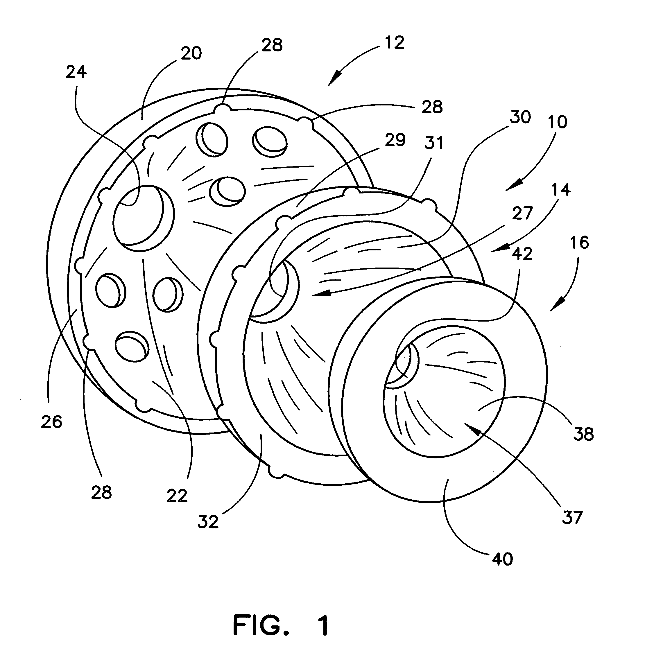
[0028]FIG. 1 shows an exploded perspective view of an exemplary modular acetabular trial 10 according to the present invention. The modular acetabular trial 10 is generally configured to be received in the acetabulum of a patient. The modular acetabular trial 10 is further configured to receive a femoral head, not shown, but which would be known in the art.

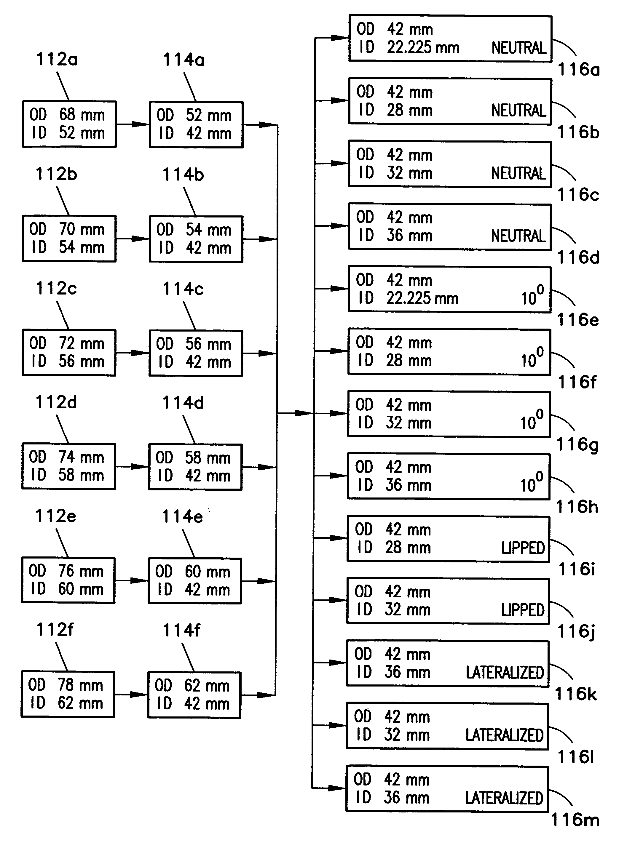
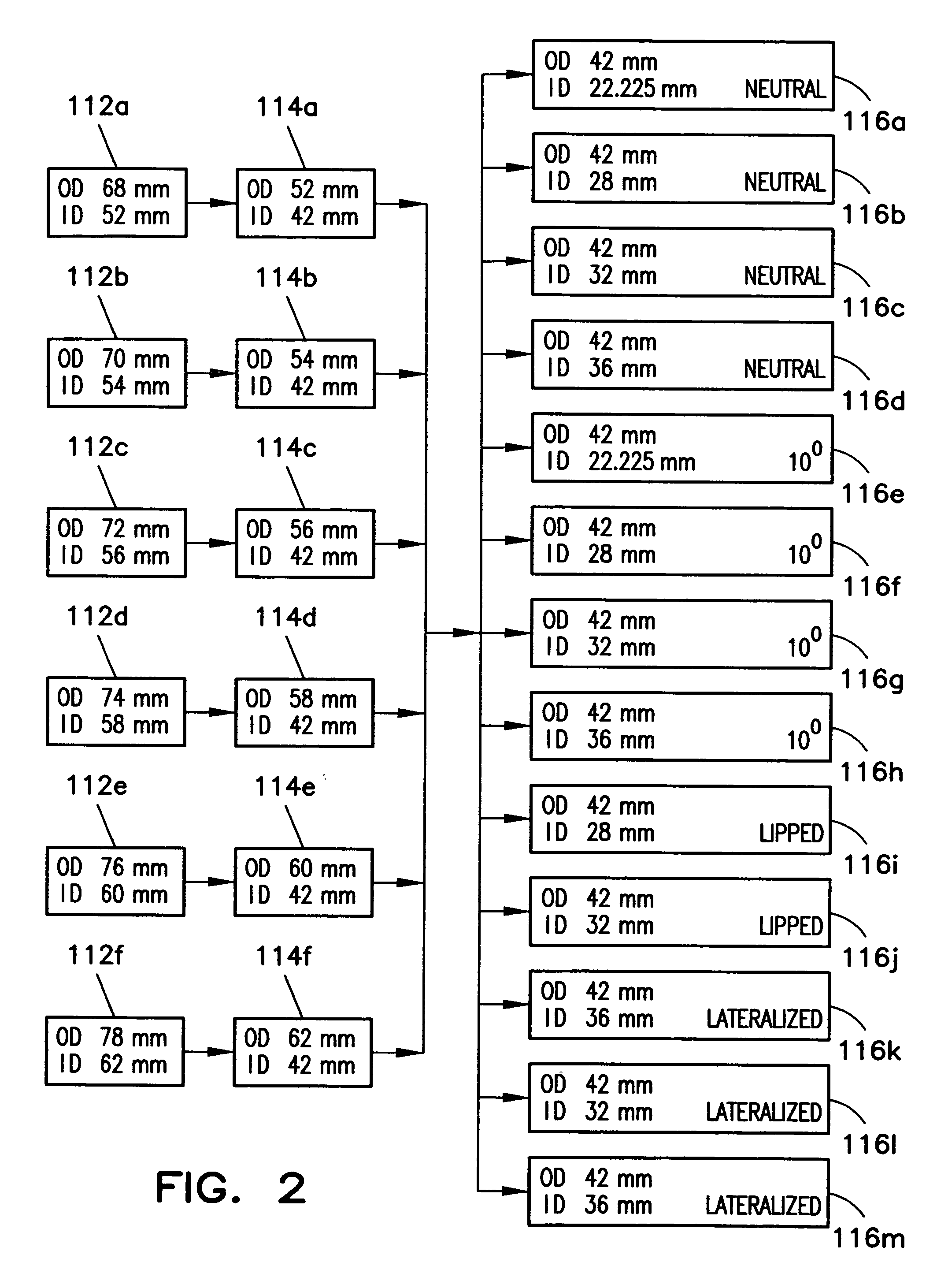
[0029] The components of the modular acetabular trial 10 are used, in whole or in part, as trial implants to ascertain the appropriate size and style of acetabular cup that will be finally implanted. In particular, the surgeon may use the components of the modular acetabular trial 10, either as a unit or as subcombinations, to determine the outer shell diameter and the inner liner style of the final acetabular cup implant.

[0030] The modular acetabular trial 10 includes an outer shell 12, an intermediate component 14 and an inner liner component 16. The outer shell 12 includes a rounded outer surface 20, which is substantially he...


PUM


Abstract

A trial implant kit includes a plurality of intermediate components and a plurality of inner components. Each of the plurality of intermediate components has a uniform inner surface, although at least two of the plurality of intermediate components having distinct outer surfaces. Each of the distinct outer surfaces is configured to engage one of a plurality of acetabular shell component geometries. Each of the plurality of inner components has a uniform outer surface portion and a bearing surface, the uniform outer surface portion configured to be received by the uniform inner surface of any of plurality of intermediate components. The bearing surface is configured to engage a femoral head. At least two of plurality of inner components having distinct bearing surface configurations.

Description

[0001] This application is a continuation of co-pending application Ser. No. 10 / 319,293, filed on Dec. 13, 2002, the disclosure of which is hereby totally incorporated by reference in its entirety for all purposes.FIELD OF THE INVENTION [0002] The present invention relates generally to prosthetic orthopaedic implants, and more particularly, to methods and apparatus for implanting modular orthopaedic implants. BACKGROUND OF THE INVENTION [0003] Many orthopaedic procedures involve the implantation of prosthetic devices to replace badly damaged or diseased bone tissue. Common orthopaedic procedures that involve prosthetic devices include total or partial hip, knee and shoulder replacement. For example, a hip replacement often involves a prosthetic femoral implant. The femoral implant usually includes a rigid stem that is secured within the natural femur bone tissue. The femoral implant further includes a rounded head that is received by, and may pivot within, a natural or artificial hi...

Claims


Application Information

Patent Timeline
Patent Type & Authority Applications(United States)
IPC IPC(8): A61B17/56A61F2/34A61F2/00A61F2/30A61F2/32A61F2/46A61F5/00
CPCA61F2/4684A61F2002/30403A61F2002/30433A61F2002/30787A61F2002/3401A61F2220/0041A61F2002/3404A61F2002/3443A61F2002/3448A61F2220/0025A61F2002/3403
Inventor LEWIS, PAUL P.KENNEDY, JAMES M.WITHEE, PHILLIP G.
Owner DEPUY PROD INC
Why Eureka
Try Eureka