

Luminous display and method of making same
- Summary
- Abstract
- Description
- Claims
- Application Information
AI Technical Summary
Problems solved by technology
Method used
Image

Examples
first embodiment
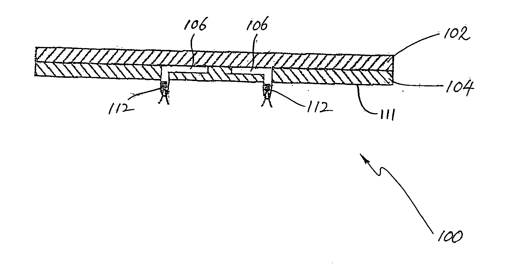
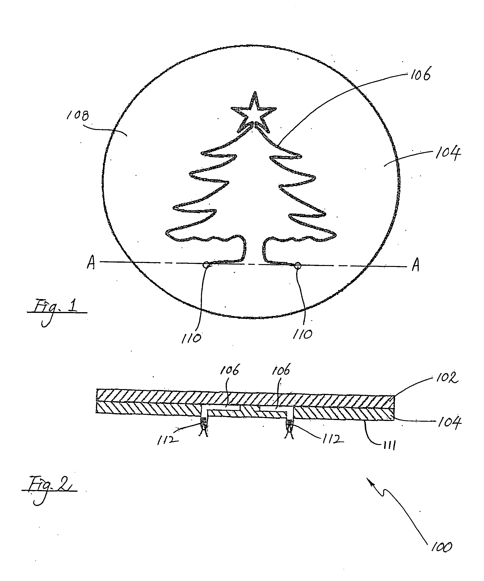
[0024] In a first embodiment according to the invention, as shown in FIGS. 1 and 2, a luminous display 100 includes a top body part 102 and a bottom body part 104. The top body part 102 is made of a non-opaque, e.g. transparent or translucent, material, e.g. glass or plastics. The top body part 102 has substantially flat upper and lower surfaces. As to the bottom body part 104, and as shown in more detail in FIG. 1, a continuous recess 106 is formed, e.g. during the moulding stage, on an upper surface 108 of the bottom body part 104 to form a pre-defined pattern, e.g. a Christmas tree as now shown in FIG. 1. It should of course be understood that various other patterns can be formed. At each of two extremities of the recess 106 is an exhaust hole 110, leading to a lower surface 111 of the bottom body part 104.
[0025] During assembly of the luminous display 100, the lower surface of the top body part 102 is fused together with the upper surface 108 of the bottom body part 104 to form ...
second embodiment
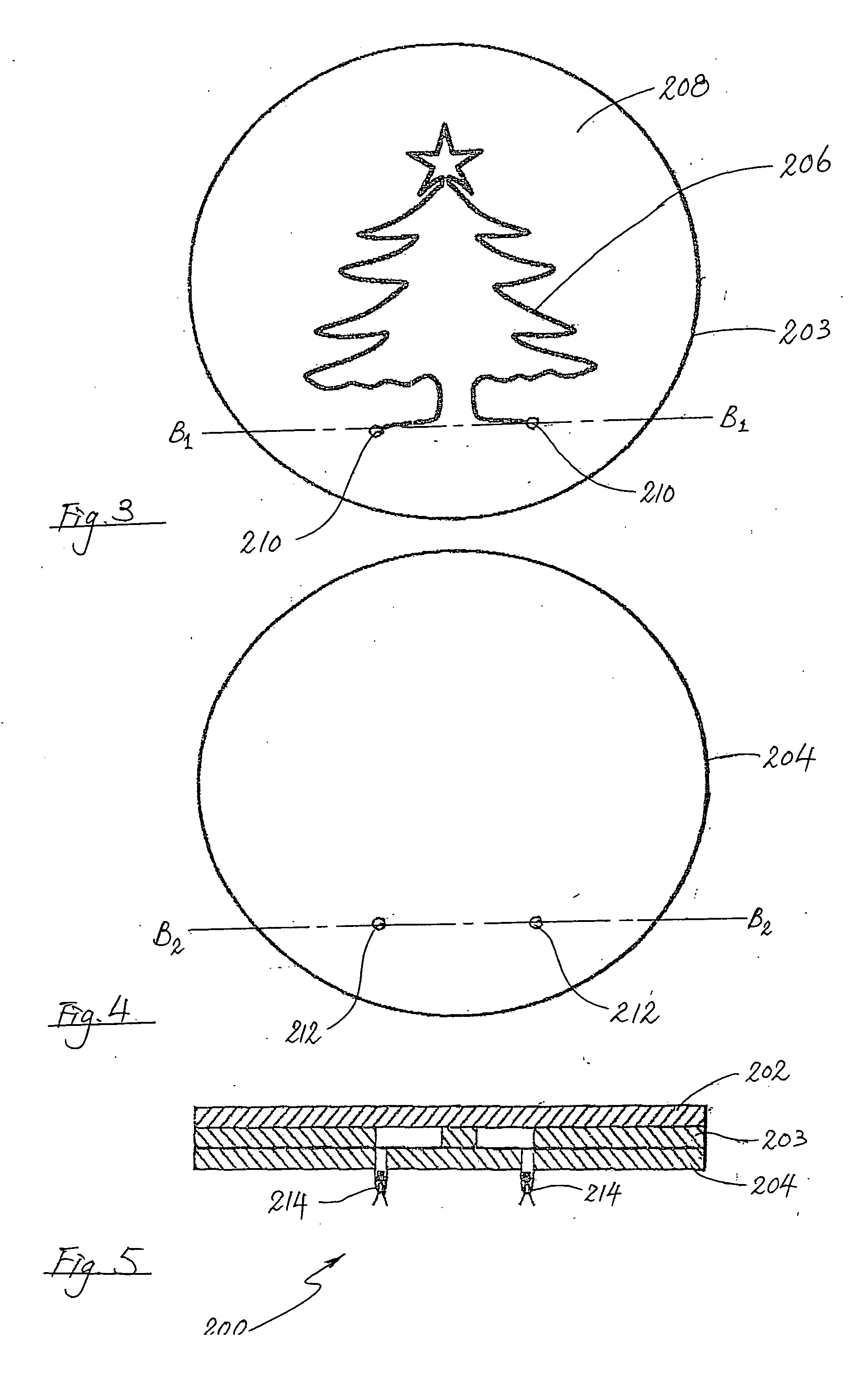
[0027] In a second embodiment according to the invention, as shown in FIGS. 3 to 5, a luminous display 200 includes a top body part 202, an intermediate body part 203 and a bottom body part 204. As in the case of the luminous display 100 discussed above, the top body part 202 is made of a non-opaque material, and has substantially flat upper and lower surfaces. As to the intermediate body part 203, and as shown in more detail in FIG. 3, a continuous recess 206 is formed, e.g. during the moulding stage, on an upper surface 208 of the intermediate body part 203 to form a pre-defined pattern, e.g. a Christmas tree as now shown in FIG. 3. At each of two extremities of the recess 206 is an opening 210, leading to a lower surface of the intermediate body part 203. As to the bottom body part 204, two through holes 212 are provided.
[0028] During assembly of the luminous display 200, the lower surface of the top body part 202 is fused together with the upper surface 208 of the intermediate b...
third embodiment
[0029] In a third embodiment according to the invention, as shown in FIGS. 6 to 8, a luminous display 300 includes a top body part 302, an intermediate body part 303 and a bottom body part 304. The top body part 302 is made of a non-opaque material, and has substantially flat upper and lower surfaces. As shown in more detail in FIG. 6, a continuous recess 306 is formed, e.g. during the moulding stage, on an upper surface 308 of the intermediate body part 303 to form a first pattern, e.g. a spider. At each of two extremities of the recess 306 is a through hole 310a, 310b. As to the bottom body part 304, and as shown in FIG. 7, a continuous recess 316 is formed, e.g. during the moulding stage, on an upper surface 318 of the bottom body part 304 to form a second pattern, e.g. a spiral. At each of two extremities of the recess 316 is a through hole 320a, 320b. A further through hole 322 is also provided in the bottom body part 304.
[0030] During assembly of the luminous display 300, the ...
PUM
 Abstract
Description
Claims
Application Information