Threaded joint for gas turbine components

Active Publication Date: 2005-11-17
ALLISON ADVANCED DEVMENT
View PDF24 Cites 10 Cited by
  • Summary
  • Abstract
  • Description
  • Claims
  • Application Information

AI Technical Summary

Benefits of technology

[0006] Another form of the present invention contemplates a method of assembling a threaded joint between two gas turbine components. The method comprising: orienting a cylindrical portion of the two components in an overlapping relationship, one of the components in the overlapping relationship defining an inner overlapping section having an externally threaded portion and the other component defining an outer overlapping section having an internally threaded portion

Problems solved by technology

One limitation of this approach has been that the prior system com

Method used


Image

  • Threaded joint for gas turbine components
  • Threaded joint for gas turbine components
  • Threaded joint for gas turbine components

Examples


Embodiment Construction

[0018] For the purposes of promoting an understanding of the principles of the invention, reference will now be made to the embodiments illustrated in the drawings and specific language will be used to describe the same. It will nevertheless be understood that no limitation of the scope of the invention is thereby intended, such alterations and further modifications in the illustrated device, and such further applications of the principles of the invention as illustrated therein being contemplated as would normally occur to one skilled in the art to which the invention relates.

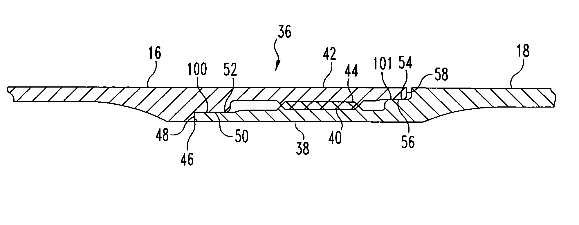
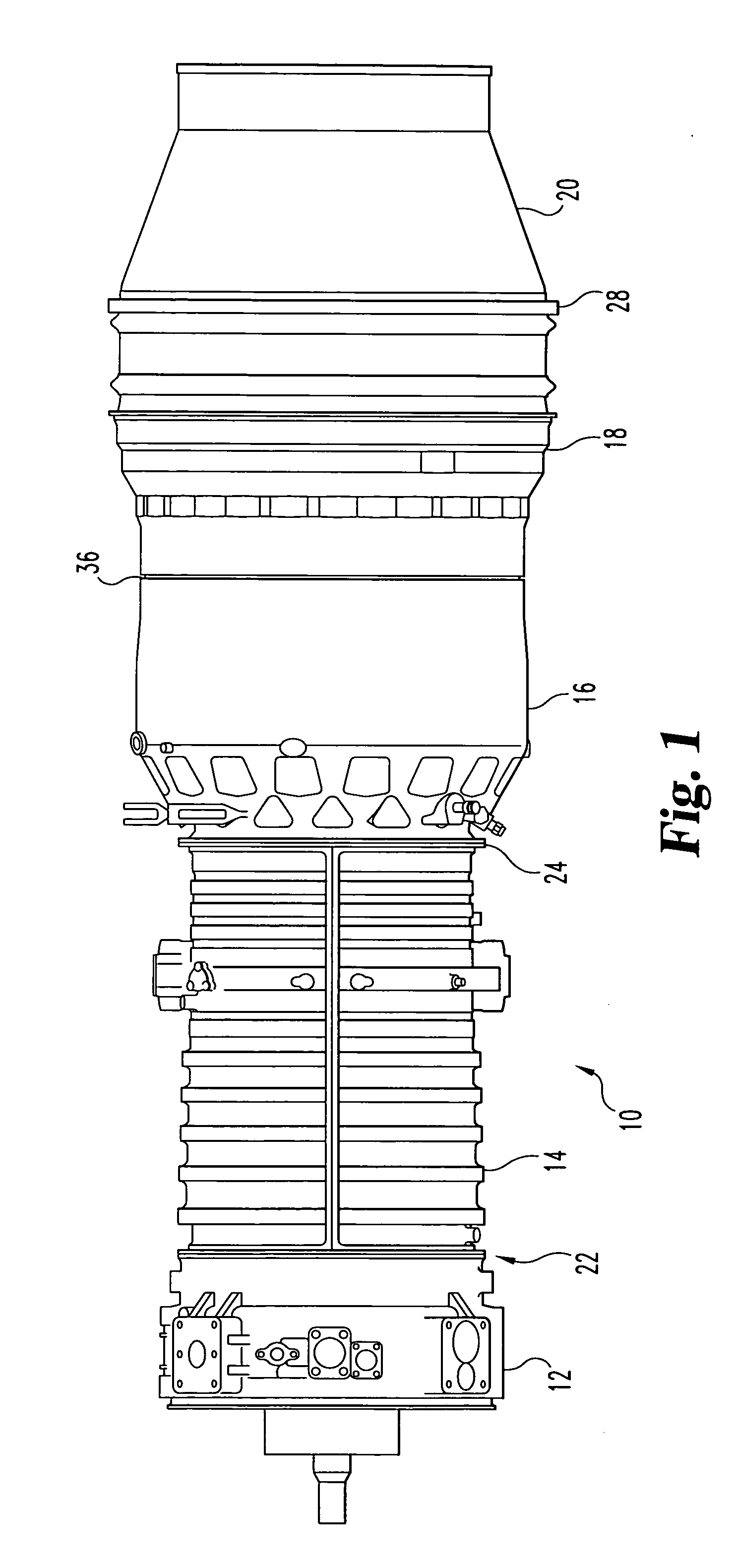
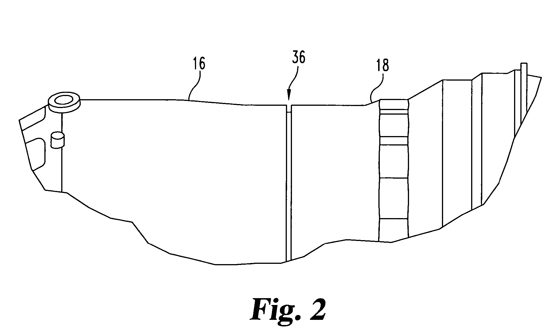
[0019] With reference to FIG. 1, there is illustrated a gas turbine engine 10 utilizing one embodiment of a threaded joint 36 of the present invention. The gas turbine engine 10 illustrated is purely illustrative and no limitation is intended herein to any specific type of gas turbine engine. The illustrative gas turbine engine comprises an accessory drive / inlet housing 12, compressor housing 14, diffuser / com...


PUM


Abstract

An assembly including inner and outer overlapping annular elements with interengaging threads. An axial abutment between the two elements is spaced from the threaded section to permit a structural and fluid seal at the joint. Pilot joints are provided to stabilize the joint and provide additional sealing.

Description

BACKGROUND OF THE INVENTION [0001] The present application relates generally to disconnectable threaded joints for interconnecting two components. More particularly, one form of the present application relates to a threaded joint for coupling together gas turbine engine casings. Although the present application was developed for application in gas turbine engines, certain applications may exist in other fields. [0002] Gas turbine engines usually include a number of cylindrical components joined together to define a housing. Within the housing, there is generally a flow of working fluid. Gas turbine engine designers have strived to secure the components of the housing in a way that maintains structural and pressure integrity while at the same time facilitating assembly and disassembly for inspection and / or repair of components. [0003] A conventional system for connecting cylindrical gas turbine engine housing components has been to incorporate circumferential and abutting flanges whi...

Claims


Application Information

Patent Timeline
IPC IPC(8): F01D11/00F02C7/28F16J15/00
CPCF01D11/00F05D2260/30F05D2240/55F02C7/28
Inventor RESS, ROBERT ANTHONY JR.
Owner ALLISON ADVANCED DEVMENT
Why Eureka
Try Eureka